Dell DX6000G Hardware Owner's Manual - Page 135
System Board, Removing the System Board
 |
View all Dell DX6000G manuals
Add to My Manuals
Save this manual to your list of manuals |
Page 135 highlights
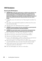
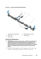
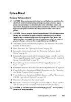
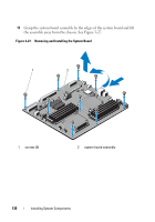
System Board Removing the System Board CAUTION: Many repairs may only be done by a certified service technician. You should only perform troubleshooting and simple repairs as authorized in your product documentation, or as directed by the online or telephone service and support team. Damage due to servicing that is not authorized by Dell is not covered by your warranty. Read and follow the safety instructions that came with the product. CAUTION: If you are using the Trusted Program Module (TPM) with an encryption key, you may be prompted to create a recovery key during program or system setup. Be sure to create and safely store this recovery key. If you replace this system board, you must supply the recovery key when you restart your system or program before you can access the encrypted data on your hard drives. 1 Turn off the system and attached peripherals, and disconnect the system from the electrical outlet. 2 Open the system. See "Opening the System" on page 80. 3 Remove the system board shroud. See "Removing the System Board Shroud" on page 98. 4 Remove all expansion cards and the integrated storage controller card. See "Removing an Expansion Card" on page 91 and "Removing the Integrated Storage Controller Card" on page 92. 5 Remove the expansion-card riser. See "Removing an Expansion-Card Riser" on page 94. 6 Remove the processor heat sinks. See "Removing a Processor" on page 118. 7 If installed, remove the optional iDRAC6 Enterprise card. See "Removing an iDRAC6 Enterprise Card" on page 104. 8 If installed, remove the optional iDRAC6 Express card. See "Removing an iDRAC6 Express Card (Optional)" on page 101. 9 Disconnect all cables from the system board. 10 Remove the nine screws securing the system board to the chassis and then slide the system board assembly toward the front end of the chassis. CAUTION: Do not lift the system board assembly by grasping a memory module, processor, or other components. Installing System Components 135
-
 1
1 -
2
-
3
-
4
-
5
-
6
-
7
-
8
-
9
-
10
-
11
-
12
-
13
-
14
-
15
-
16
-
17
-
18
-
19
-
20
-
21
-
22
-
23
-
24
-
25
-
26
-
27
-
28
-
29
-
30
-
31
-
32
-
33
-
34
-
35
-
36
-
37
-
38
-
39
-
40
-
41
-
42
-
43
-
44
-
45
-
46
-
47
-
48
-
49
-
50
-
51
-
52
-
53
-
54
-
55
-
56
-
57
-
58
-
59
-
60
-
61
-
62
-
63
-
64
-
65
-
66
-
67
-
68
-
69
-
70
-
71
-
72
-
73
-
74
-
75
-
76
-
77
-
78
-
79
-
80
-
81
-
82
-
83
-
84
-
85
-
86
-
87
-
88
-
89
-
90
-
91
-
92
-
93
-
94
-
95
-
96
-
97
-
98
-
99
-
100
-
101
-
102
-
103
-
104
-
105
-
106
-
107
-
108
-
109
-
110
-
111
-
112
-
113
-
114
-
115
-
116
-
117
-
118
-
119
-
120
-
121
-
122
-
123
-
124
-
125
-
126
-
127
-
128
-
129
-
 130
130 -
 131
131 -
 132
132 -
 133
133 -
 134
134 -
 135
135 -
 136
136 -
 137
137 -
 138
138 -
 139
139 -
 140
140 -
141
-
142
-
143
-
144
-
145
-
146
-
147
-
148
-
149
-
150
-
151
-
152
-
153
-
154
-
155
-
156
-
157
-
158
-
159
-
160
-
161
-
162
-
163
-
164
-
165
-
166
-
167
-
168
-
169
-
170
-
171
-
172
-
173
-
174
 |
 |