Dell DX6000G Hardware Owner's Manual - Page 94
Expansion-Card Riser, Removing an Expansion-Card Riser
 |
View all Dell DX6000G manuals
Add to My Manuals
Save this manual to your list of manuals |
Page 94 highlights
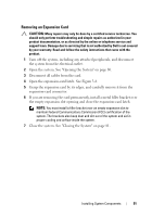
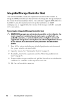
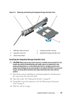
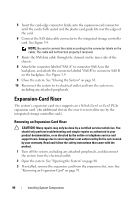
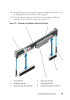
5 Insert the card-edge connector firmly into the expansion-card connector until the card is fully seated and the plastic card guide fits over the edges of the card. 6 Connect the SAS data cable connector to the integrated storage controller card. See Figure 3-9. NOTE: Be sure to connect the cable according to the connector labels on the cable. The cable will not function properly if reversed. 7 Route the SAS data cable through the channel on the inner side of the chassis. 8 Attach the connector labeled "SAS A" to connector SAS A on the backplane, and attach the connector labeled "SAS B" to connector SAS B on the backplane. See Figure 3-9. 9 Close the system. See "Closing the System" on page 81. 10 Reconnect the system to its electrical outlet and turn the system on, including any attached peripherals. Expansion-Card Riser The system's expansion-card riser supports an x16 link Gen1 or Gen2 PCIe expansion card. (An additional slot on the riser is reserved for use by the integrated storage controller card.) Removing an Expansion-Card Riser CAUTION: Many repairs may only be done by a certified service technician. You should only perform troubleshooting and simple repairs as authorized in your product documentation, or as directed by the online or telephone service and support team. Damage due to servicing that is not authorized by Dell is not covered by your warranty. Read and follow the safety instructions that came with the product. 1 Turn off the system, including any attached peripherals, and disconnect the system from the electrical outlet. 2 Open the system. See "Opening the System" on page 80. 3 If installed, remove the expansion card from the expansion slot, now. See "Removing an Expansion Card" on page 91. 94 Installing System Components
-
 1
1 -
2
-
3
-
4
-
5
-
6
-
7
-
8
-
9
-
10
-
11
-
12
-
13
-
14
-
15
-
16
-
17
-
18
-
19
-
20
-
21
-
22
-
23
-
24
-
25
-
26
-
27
-
28
-
29
-
30
-
31
-
32
-
33
-
34
-
35
-
36
-
37
-
38
-
39
-
40
-
41
-
42
-
43
-
44
-
45
-
46
-
47
-
48
-
49
-
50
-
51
-
52
-
53
-
54
-
55
-
56
-
57
-
58
-
59
-
60
-
61
-
62
-
63
-
64
-
65
-
66
-
67
-
68
-
69
-
70
-
71
-
72
-
73
-
74
-
75
-
76
-
77
-
78
-
79
-
80
-
81
-
82
-
83
-
84
-
85
-
86
-
87
-
88
-
 89
89 -
 90
90 -
 91
91 -
 92
92 -
 93
93 -
 94
94 -
 95
95 -
 96
96 -
 97
97 -
 98
98 -
 99
99 -
100
-
101
-
102
-
103
-
104
-
105
-
106
-
107
-
108
-
109
-
110
-
111
-
112
-
113
-
114
-
115
-
116
-
117
-
118
-
119
-
120
-
121
-
122
-
123
-
124
-
125
-
126
-
127
-
128
-
129
-
130
-
131
-
132
-
133
-
134
-
135
-
136
-
137
-
138
-
139
-
140
-
141
-
142
-
143
-
144
-
145
-
146
-
147
-
148
-
149
-
150
-
151
-
152
-
153
-
154
-
155
-
156
-
157
-
158
-
159
-
160
-
161
-
162
-
163
-
164
-
165
-
166
-
167
-
168
-
169
-
170
-
171
-
172
-
173
-
174
 |
 |