Dell DX6000G Hardware Owner's Manual - Page 137
Installing the System Board, Installing Memory Modules
 |
View all Dell DX6000G manuals
Add to My Manuals
Save this manual to your list of manuals |
Page 137 highlights
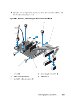
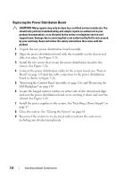
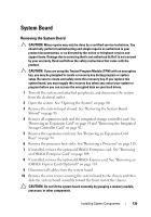
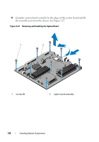
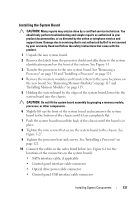
Installing the System Board CAUTION: Many repairs may only be done by a certified service technician. You should only perform troubleshooting and simple repairs as authorized in your product documentation, or as directed by the online or telephone service and support team. Damage due to servicing that is not authorized by Dell is not covered by your warranty. Read and follow the safety instructions that came with the product. 1 Unpack the new system board. 2 Remove the labels from the processor shield and affix them to the system identification panel on the front of the system. See Figure 1-1. 3 Transfer the processors to the new system board. See "Removing a Processor" on page 118 and "Installing a Processor" on page 121. 4 Remove the memory modules and transfer them to the same locations on the new board. See "Removing Memory Modules" on page 117 and "Installing Memory Modules" on page 115. 5 Holding the system board by the edges of the system board, lower the the system board into the chassis. CAUTION: Do not lift the system board assembly by grasping a memory module, processor, or other components. 6 Slightly lift up the front of the system board and maneuver the system board to the bottom of the chassis until it lays completely flat. 7 Push the system board toward the back of the chassis until the board is in place. 8 Tighten the nine screws that secure the system board to the chassis. See Figure 3-27. 9 Tighten the processor heat sink screws. See "Installing a Processor" on page 121. 10 Connect the cables in the order listed below (see Figure 6-1 for the locations of the connectors on the system board): • SATA interface cable, if applicable • Control panel interface cable connector • Optical drive power cable connector • Control panel USB interface cable connector Installing System Components 137
-
 1
1 -
2
-
3
-
4
-
5
-
6
-
7
-
8
-
9
-
10
-
11
-
12
-
13
-
14
-
15
-
16
-
17
-
18
-
19
-
20
-
21
-
22
-
23
-
24
-
25
-
26
-
27
-
28
-
29
-
30
-
31
-
32
-
33
-
34
-
35
-
36
-
37
-
38
-
39
-
40
-
41
-
42
-
43
-
44
-
45
-
46
-
47
-
48
-
49
-
50
-
51
-
52
-
53
-
54
-
55
-
56
-
57
-
58
-
59
-
60
-
61
-
62
-
63
-
64
-
65
-
66
-
67
-
68
-
69
-
70
-
71
-
72
-
73
-
74
-
75
-
76
-
77
-
78
-
79
-
80
-
81
-
82
-
83
-
84
-
85
-
86
-
87
-
88
-
89
-
90
-
91
-
92
-
93
-
94
-
95
-
96
-
97
-
98
-
99
-
100
-
101
-
102
-
103
-
104
-
105
-
106
-
107
-
108
-
109
-
110
-
111
-
112
-
113
-
114
-
115
-
116
-
117
-
118
-
119
-
120
-
121
-
122
-
123
-
124
-
125
-
126
-
127
-
128
-
129
-
130
-
131
-
 132
132 -
 133
133 -
 134
134 -
 135
135 -
 136
136 -
 137
137 -
 138
138 -
 139
139 -
 140
140 -
 141
141 -
 142
142 -
143
-
144
-
145
-
146
-
147
-
148
-
149
-
150
-
151
-
152
-
153
-
154
-
155
-
156
-
157
-
158
-
159
-
160
-
161
-
162
-
163
-
164
-
165
-
166
-
167
-
168
-
169
-
170
-
171
-
172
-
173
-
174
 |
 |