Dell PowerEdge 1955 Hardware Owner's Manual (PDF) - Page 111
Inside the Server Module, During an installation or troubleshooting procedure
 |
View all Dell PowerEdge 1955 manuals
Add to My Manuals
Save this manual to your list of manuals |
Page 111 highlights
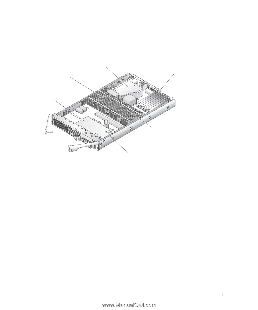
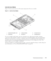
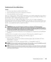
Inside the Server Module Figure 4-1 shows an interior view of the major components of the server module. Figure 4-1. Inside the Server Module 1 2 6 5 3 4 1 optional I/O daughter card 4 hard drive 0 2 memory modules 5 hard drive 1 3 microprocessor 2 6 microprocessor 1 The server module board contains up to two microprocessors, eight memory modules, interface connectors for the hard drives, interface connectors for an optional daughter card, and a dual-Gigabit NIC. Up to two hard drives connect to a controller on the server module board. If two hard drives are installed, you have the option of enabling integrated mirroring. See the Configuration Guide. This feature enables you to have RAID 1 capabilities. During an installation or troubleshooting procedure, you may be required to change a switch setting. For more information, see "Server Module Board DIP Switch" on page 122. Troubleshooting Your System 111
-
 1
1 -
2
-
3
-
4
-
5
-
6
-
7
-
8
-
9
-
10
-
11
-
12
-
13
-
14
-
15
-
16
-
17
-
18
-
19
-
20
-
21
-
22
-
23
-
24
-
25
-
26
-
27
-
28
-
29
-
30
-
31
-
32
-
33
-
34
-
35
-
36
-
37
-
38
-
39
-
40
-
41
-
42
-
43
-
44
-
45
-
46
-
47
-
48
-
49
-
50
-
51
-
52
-
53
-
54
-
55
-
56
-
57
-
58
-
59
-
60
-
61
-
62
-
63
-
64
-
65
-
66
-
67
-
68
-
69
-
70
-
71
-
72
-
73
-
74
-
75
-
76
-
77
-
78
-
79
-
80
-
81
-
82
-
83
-
84
-
85
-
86
-
87
-
88
-
89
-
90
-
91
-
92
-
93
-
94
-
95
-
96
-
97
-
98
-
99
-
100
-
101
-
102
-
103
-
104
-
105
-
 106
106 -
 107
107 -
 108
108 -
 109
109 -
 110
110 -
 111
111 -
 112
112 -
 113
113 -
 114
114 -
 115
115 -
 116
116 -
117
-
118
-
119
-
120
-
121
-
122
-
123
-
124
-
125
-
126
-
127
-
128
-
129
-
130
-
131
-
132
-
133
-
134
-
135
-
136
-
137
-
138
-
139
-
140
-
141
-
142
-
143
-
144
-
145
-
146
-
147
-
148
-
149
-
150
-
151
-
152
-
153
-
154
-
155
-
156
-
157
-
158
-
159
-
160
 |
 |