Dell PowerEdge 1955 Hardware Owner's Manual (PDF) - Page 82
I/O Module Daughter Card, daughter cards, including a TCP/IP Offload Engine TOE NIC daughtercard.
 |
View all Dell PowerEdge 1955 manuals
Add to My Manuals
Save this manual to your list of manuals |
Page 82 highlights
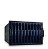
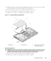
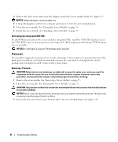
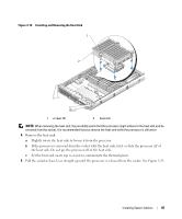
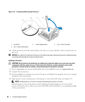
Removing Memory Modules CAUTION: Only trained service technicians are authorized to remove the system cover and access any of the components inside the system. See your Product Information Guide for complete information about safety precautions, working inside the computer, and protecting against electrostatic discharge. CAUTION: The DIMMs are hot to the touch for some time after the system has been powered down. Allow time for the DIMMs to cool before handling them. Handle the DIMMs by the card edges and avoid touching the DIMM components. 1 Remove the server module. See "Removing a Server Module" on page 73. 2 Open the server module. See "Opening the Server Module" on page 75. 3 Locate the memory module sockets. See Figure 6-3. 4 Press down and out on the ejectors on each end of the socket until the memory module pops out of the socket. See Figure 3-16. 5 Close the server module. See "Closing the Server Module" on page 76. 6 Install the server module. See "Installing a Server Module" on page 74. I/O Module Daughter Card The server module board daughter-card connectors support a variety of dual-channel I/O module daughter cards, including a TCP/IP Offload Engine (TOE) NIC daughtercard. • If installed, the daughter card must be used in conjunction with its appropriate back-panel I/O module and connector number. For example, server module number 5 must have a Fibre Channel daughter card installed to communicate with the Fibre Channel pass-through module connector number 5 (primary and secondary bays). • You cannot install daughter cards of different fabric types within a system. For more information on I/O module daughter cards, see "Guidelines for Installing Connectivity Modules" on page 28. Installing a Daughter Card CAUTION: Many repairs may only be done by a certified service technician. You should only perform troubleshooting and simple repairs as authorized in your product documentation, or as directed by the online or telephone service and support team. Damage due to servicing that is not authorized by Dell is not covered by your warranty. Read and follow the safety instructions that came with the product. 1 Remove the server module. See "Removing a Server Module" on page 73. 2 Open the server module. See "Opening the Server Module" on page 75. NOTICE: Hold the daughter card by its edges only. 3 Align the three screw holes on the daughter card with the three standoffs on the server module board. See Figure 3-17. 82 Installing System Options
-
 1
1 -
2
-
3
-
4
-
5
-
6
-
7
-
8
-
9
-
10
-
11
-
12
-
13
-
14
-
15
-
16
-
17
-
18
-
19
-
20
-
21
-
22
-
23
-
24
-
25
-
26
-
27
-
28
-
29
-
30
-
31
-
32
-
33
-
34
-
35
-
36
-
37
-
38
-
39
-
40
-
41
-
42
-
43
-
44
-
45
-
46
-
47
-
48
-
49
-
50
-
51
-
52
-
53
-
54
-
55
-
56
-
57
-
58
-
59
-
60
-
61
-
62
-
63
-
64
-
65
-
66
-
67
-
68
-
69
-
70
-
71
-
72
-
73
-
74
-
75
-
76
-
 77
77 -
 78
78 -
 79
79 -
 80
80 -
 81
81 -
 82
82 -
 83
83 -
 84
84 -
 85
85 -
 86
86 -
 87
87 -
88
-
89
-
90
-
91
-
92
-
93
-
94
-
95
-
96
-
97
-
98
-
99
-
100
-
101
-
102
-
103
-
104
-
105
-
106
-
107
-
108
-
109
-
110
-
111
-
112
-
113
-
114
-
115
-
116
-
117
-
118
-
119
-
120
-
121
-
122
-
123
-
124
-
125
-
126
-
127
-
128
-
129
-
130
-
131
-
132
-
133
-
134
-
135
-
136
-
137
-
138
-
139
-
140
-
141
-
142
-
143
-
144
-
145
-
146
-
147
-
148
-
149
-
150
-
151
-
152
-
153
-
154
-
155
-
156
-
157
-
158
-
159
-
160
 |
 |