Dell PowerEdge 1955 Hardware Owner's Manual (PDF) - Page 121
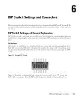
DIP Switch Settings and Connectors, DIP Switch Settings-A General Explanation, DIP Switches
 |
View all Dell PowerEdge 1955 manuals
Add to My Manuals
Save this manual to your list of manuals |
Page 121 highlights
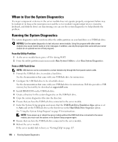
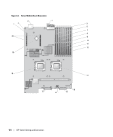
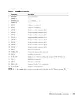
DIP Switch Settings and Connectors This section provides detailed information about the sever-module board DIP switch settings. It also provides some basic information on switches and describes the connectors on the various boards in the system. DIP Switch Settings-A General Explanation DIP switches provide a convenient and reversible way of reconfiguring the circuitry on a printed circuit board. When reconfiguring the system, you may need to change DIP switch settings on circuit boards or drives. DIP Switches DIP switches are small blocks on a circuit board with one or more slide switches emerging from them. Each slide switch on the DIP switch is designated by a number. To change a DIP switch setting, move the appropriate slide switch to either the "on" or "off" position. Figure 6-1 shows an example of a DIP switch. Figure 6-1. Example DIP Switch ON DIP 123456 Figure 6-2 shows the location and default settings of the sever-module board DIP switch. See Table 6-1 for information about the DIP switch designations, default settings, and functions. DIP Switch Settings and Connectors 121
-
 1
1 -
2
-
3
-
4
-
5
-
6
-
7
-
8
-
9
-
10
-
11
-
12
-
13
-
14
-
15
-
16
-
17
-
18
-
19
-
20
-
21
-
22
-
23
-
24
-
25
-
26
-
27
-
28
-
29
-
30
-
31
-
32
-
33
-
34
-
35
-
36
-
37
-
38
-
39
-
40
-
41
-
42
-
43
-
44
-
45
-
46
-
47
-
48
-
49
-
50
-
51
-
52
-
53
-
54
-
55
-
56
-
57
-
58
-
59
-
60
-
61
-
62
-
63
-
64
-
65
-
66
-
67
-
68
-
69
-
70
-
71
-
72
-
73
-
74
-
75
-
76
-
77
-
78
-
79
-
80
-
81
-
82
-
83
-
84
-
85
-
86
-
87
-
88
-
89
-
90
-
91
-
92
-
93
-
94
-
95
-
96
-
97
-
98
-
99
-
100
-
101
-
102
-
103
-
104
-
105
-
106
-
107
-
108
-
109
-
110
-
111
-
112
-
113
-
114
-
115
-
 116
116 -
 117
117 -
 118
118 -
 119
119 -
 120
120 -
 121
121 -
 122
122 -
 123
123 -
 124
124 -
 125
125 -
 126
126 -
127
-
128
-
129
-
130
-
131
-
132
-
133
-
134
-
135
-
136
-
137
-
138
-
139
-
140
-
141
-
142
-
143
-
144
-
145
-
146
-
147
-
148
-
149
-
150
-
151
-
152
-
153
-
154
-
155
-
156
-
157
-
158
-
159
-
160
 |
 |