Dell PowerEdge 1955 Hardware Owner's Manual (PDF) - Page 29
PowerConnect 5316M Ethernet Switch Module, Table 1-9., Valid I/O Module Configurations
 |
View all Dell PowerEdge 1955 manuals
Add to My Manuals
Save this manual to your list of manuals |
Page 29 highlights
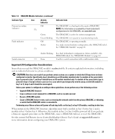
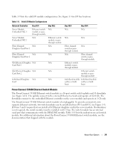
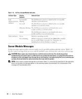
Table 1-9 lists the valid I/O module configurations. See Figure 1-5 for I/O bay locations. Table 1-9. Valid I/O Module Configurations Network Controller Server Module Embedded NIC 1 Server Module Embedded NIC 2 Bay IO/1 Ethernet switch module or passthrough module N/A Fibre Channel N/A Daughter Card Port 1 Bay IO/2 N/A Ethernet switch module or passthrough module N/A Fibre Channel N/A N/A Daughter Card Port 2 Gb Ethernet Daughter N/A N/A Card Port 1 Gb Ethernet Daughter N/A N/A Card Port 2 Infiniband Daughter N/A N/A Card Bay IO/3 N/A Bay IO/4 N/A N/A N/A Fibre channel N/A switch or pass- through module N/A Fibre channel switch or pass- through module Ethernet switch module or passthrough module Ethernet switch module or passthrough module Infiniband module Infiniband module (either or both (either or both bays) bays) PowerConnect 5316M Ethernet Switch Module The PowerConnect 5316M Ethernet switch module is a 16-port switch with 6 uplinks and 10 downlinks (see Figure 1-11). The uplinks connect to the external Ethernet network and operate at 1/2/4 Gb. The downlinks connect to the embedded Ethernet controller on the server module and operate at 1 Gb only. The PowerConnect 5316M Ethernet switch module is hot-pluggable. To provide connectivity into separate Ethernet networks, two switch modules can be installed in bays I/O 1 and I/O 2 (see Figure 1-5). I/O bays 3 and 4 require that you install a Gb Ethernet daughter card in the server module. If redundancy is not required, the switch module must be installed in I/O 1 bay. The switch module has an internal serial port that communicates with the DRAC/MC module. Table 1-10 lists the indicators on each switch module. For additional information about the PowerConnect 5316M Ethernet switch module, see the documentation that shipped with the module. About Your System 29
-
 1
1 -
2
-
3
-
4
-
5
-
6
-
7
-
8
-
9
-
10
-
11
-
12
-
13
-
14
-
15
-
16
-
17
-
18
-
19
-
20
-
21
-
22
-
23
-
 24
24 -
 25
25 -
 26
26 -
 27
27 -
 28
28 -
 29
29 -
 30
30 -
 31
31 -
 32
32 -
 33
33 -
 34
34 -
35
-
36
-
37
-
38
-
39
-
40
-
41
-
42
-
43
-
44
-
45
-
46
-
47
-
48
-
49
-
50
-
51
-
52
-
53
-
54
-
55
-
56
-
57
-
58
-
59
-
60
-
61
-
62
-
63
-
64
-
65
-
66
-
67
-
68
-
69
-
70
-
71
-
72
-
73
-
74
-
75
-
76
-
77
-
78
-
79
-
80
-
81
-
82
-
83
-
84
-
85
-
86
-
87
-
88
-
89
-
90
-
91
-
92
-
93
-
94
-
95
-
96
-
97
-
98
-
99
-
100
-
101
-
102
-
103
-
104
-
105
-
106
-
107
-
108
-
109
-
110
-
111
-
112
-
113
-
114
-
115
-
116
-
117
-
118
-
119
-
120
-
121
-
122
-
123
-
124
-
125
-
126
-
127
-
128
-
129
-
130
-
131
-
132
-
133
-
134
-
135
-
136
-
137
-
138
-
139
-
140
-
141
-
142
-
143
-
144
-
145
-
146
-
147
-
148
-
149
-
150
-
151
-
152
-
153
-
154
-
155
-
156
-
157
-
158
-
159
-
160
 |
 |