Dell PowerEdge 1955 Hardware Owner's Manual (PDF) - Page 28
DRAC/MC Firmware Requirements, I/O Connectivity, Guidelines for Installing Connectivity Modules - to daughter card
 |
View all Dell PowerEdge 1955 manuals
Add to My Manuals
Save this manual to your list of manuals |
Page 28 highlights
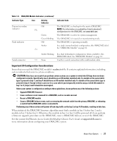
DRAC/MC Firmware Requirements The minimum DRAC/MC firmware requirement for your system is version 1.3 or later. If you are adding a second DRAC/MC module with version 1.0 to support redundancy, you must upgrade the module's firmware to version 1.1, then upgrade the firmware to version 1.3 (or later). NOTE: A DRAC/MC module's firmware version is displayed on its web-based GUI or by typing the command getsysinfo or racadm getsysinfo. See the latest Dell Remote Access Controller/Modular Chassis User's Guide at support.dell.com for more information about firmware updates and installing redundant DRAC/MC modules. This guide also provides complete instructions on how to set up and operate that version of the module. I/O Connectivity The system offers several options for connectivity through a combination of embedded Ethernet controllers, optional I/O daughter cards on the server module, and chassis I/O modules in the rear of the chassis. An I/O module's green system/diagnostic indicator is off when the module is properly operating or is off and blinks when the module is not properly operating. Guidelines for Installing Connectivity Modules The following guidelines must be used when populating I/O modules. See Figure 1-5 for I/O bay locations. • Insert a connectivity module into I/O bay 1 before installing a connectivity module into I/O bay 2. Ensure that the connectivity modules installed in I/O bays 1 and 2 are of the same fabric type. • Insert a connectivity module into I/O bay 3 before installing a connectivity module into I/O bay 4. Ensure that the connectivity modules installed in I/O bays 3 and 4 are of the same fabric type. • I/O bay 3 connects to port 1 on the daughter card (optional) installed in the server module. - This bay must be populated if there is a daughter card installed in the server module. - The type of I/O module installed in this bay must match the type of daughter card installed in the server module. For example, a Fibre Channel I/O module requires that a Fibre Channel daughter card be installed in the server module. 28 About Your System
-
 1
1 -
2
-
3
-
4
-
5
-
6
-
7
-
8
-
9
-
10
-
11
-
12
-
13
-
14
-
15
-
16
-
17
-
18
-
19
-
20
-
21
-
22
-
 23
23 -
 24
24 -
 25
25 -
 26
26 -
 27
27 -
 28
28 -
 29
29 -
 30
30 -
 31
31 -
 32
32 -
 33
33 -
34
-
35
-
36
-
37
-
38
-
39
-
40
-
41
-
42
-
43
-
44
-
45
-
46
-
47
-
48
-
49
-
50
-
51
-
52
-
53
-
54
-
55
-
56
-
57
-
58
-
59
-
60
-
61
-
62
-
63
-
64
-
65
-
66
-
67
-
68
-
69
-
70
-
71
-
72
-
73
-
74
-
75
-
76
-
77
-
78
-
79
-
80
-
81
-
82
-
83
-
84
-
85
-
86
-
87
-
88
-
89
-
90
-
91
-
92
-
93
-
94
-
95
-
96
-
97
-
98
-
99
-
100
-
101
-
102
-
103
-
104
-
105
-
106
-
107
-
108
-
109
-
110
-
111
-
112
-
113
-
114
-
115
-
116
-
117
-
118
-
119
-
120
-
121
-
122
-
123
-
124
-
125
-
126
-
127
-
128
-
129
-
130
-
131
-
132
-
133
-
134
-
135
-
136
-
137
-
138
-
139
-
140
-
141
-
142
-
143
-
144
-
145
-
146
-
147
-
148
-
149
-
150
-
151
-
152
-
153
-
154
-
155
-
156
-
157
-
158
-
159
-
160
 |
 |
