Dell PowerEdge 1955 Hardware Owner's Manual (PDF) - Page 19
Power Supply Indicator
 |
View all Dell PowerEdge 1955 manuals
Add to My Manuals
Save this manual to your list of manuals |
Page 19 highlights
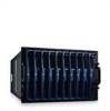
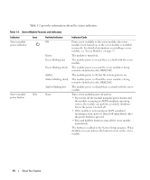
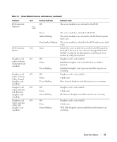
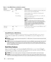
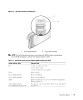
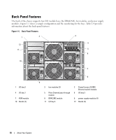
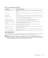
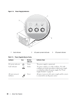
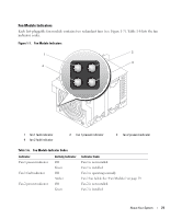
Table 1-4. Back-Panel Features and Indicators Component Power supply modules Fan modules KVM module DRAC/MC module PowerConnect™ 5316M Ethernet switch module Fibre Channel pass-through module Fibre Channel switch module Infiniband pass-through module Gb pass-through module Indicator Description Provide information about power status (see "Power Supply Indicator Codes" on page 20). Provide information about status of the system fans (see "Fan Module Indicators" on page 21). Provides information about the KVM module (see "KVM Modules" on page 22). Provides information about system status, system management status, and port status (see "DRAC/MC Module" on page 26). Provides information about the 10/100/1000 BASE-T network status (see "PowerConnect 5316M Ethernet Switch Module" on page 29). Provides information about the Fibre Channel network status (see "Fibre Channel Pass-Through Module" on page 31). Provides information about the Fibre Channel network status (see "Fibre Channel Switch Module" on page 32). Provides information about the Infiniband network status (see "Infiniband Passthrough Module" on page 32). Provides information about the network status (see "Gb Ethernet Pass-through Module" on page 33). Power Supply Indicator Each hot-pluggable power supply has indicators that provide information about power status, fault, and the presence of AC power (see Figure 1-6). Table 1-5 lists the power supply indicator codes. NOTE: Only 2100-W power supply modules are supported on your system. The 2100-W power supply modules require 180-240 V input from a PDU capable of providing AC current up to 29.2 A at 180 V input. If the power supply modules are plugged into 110-V electrical outlets, the system will not power up. About Your System 19
-
 1
1 -
2
-
3
-
4
-
5
-
6
-
7
-
8
-
9
-
10
-
11
-
12
-
13
-
 14
14 -
 15
15 -
 16
16 -
 17
17 -
 18
18 -
 19
19 -
 20
20 -
 21
21 -
 22
22 -
 23
23 -
 24
24 -
25
-
26
-
27
-
28
-
29
-
30
-
31
-
32
-
33
-
34
-
35
-
36
-
37
-
38
-
39
-
40
-
41
-
42
-
43
-
44
-
45
-
46
-
47
-
48
-
49
-
50
-
51
-
52
-
53
-
54
-
55
-
56
-
57
-
58
-
59
-
60
-
61
-
62
-
63
-
64
-
65
-
66
-
67
-
68
-
69
-
70
-
71
-
72
-
73
-
74
-
75
-
76
-
77
-
78
-
79
-
80
-
81
-
82
-
83
-
84
-
85
-
86
-
87
-
88
-
89
-
90
-
91
-
92
-
93
-
94
-
95
-
96
-
97
-
98
-
99
-
100
-
101
-
102
-
103
-
104
-
105
-
106
-
107
-
108
-
109
-
110
-
111
-
112
-
113
-
114
-
115
-
116
-
117
-
118
-
119
-
120
-
121
-
122
-
123
-
124
-
125
-
126
-
127
-
128
-
129
-
130
-
131
-
132
-
133
-
134
-
135
-
136
-
137
-
138
-
139
-
140
-
141
-
142
-
143
-
144
-
145
-
146
-
147
-
148
-
149
-
150
-
151
-
152
-
153
-
154
-
155
-
156
-
157
-
158
-
159
-
160
 |
 |