Dell PowerEdge 1955 Hardware Owner's Manual (PDF) - Page 26
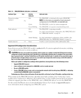
DRAC/MC Module, DRAC/MC Module Features, Table 1-8., Indicator Type, Activity, Indicator - specifications
 |
View all Dell PowerEdge 1955 manuals
Add to My Manuals
Save this manual to your list of manuals |
Page 26 highlights
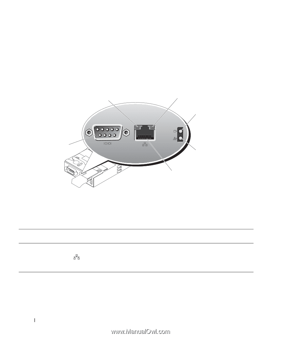
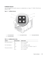
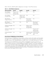
DRAC/MC Module The DRAC/MC provides serial and Ethernet management ports, a status indicator when redundant DRAC/MCs are installed (when available), and status indicators for the DRAC/MC and for the link to the system's onboard network interface controller (see Figure 1-10). See the documentation for the DRAC/MC module for specific information on serial port redirection of server modules and switches. Table 1-8 provides information about the status indicators. Figure 1-10. DRAC/MC Module Features 1 2 3 6 4 5 1 link indicator 4 fault indicator 2 activity indicator 3 primary/secondary indicator 5 network interface controller 6 serial connector Table 1-8. DRAC/MC Module Indicators Indicator Type Icon Network interface controller link indicator Activity Indicator Off Network interface controller activity indicator Green Off Amber blinking Indicator Code LAN is not linked. LAN is linked. LAN is not active. Indicates that the system DRAC/MC and the LAN are communicating. 26 About Your System
-
 1
1 -
2
-
3
-
4
-
5
-
6
-
7
-
8
-
9
-
10
-
11
-
12
-
13
-
14
-
15
-
16
-
17
-
18
-
19
-
20
-
 21
21 -
 22
22 -
 23
23 -
 24
24 -
 25
25 -
 26
26 -
 27
27 -
 28
28 -
 29
29 -
 30
30 -
 31
31 -
32
-
33
-
34
-
35
-
36
-
37
-
38
-
39
-
40
-
41
-
42
-
43
-
44
-
45
-
46
-
47
-
48
-
49
-
50
-
51
-
52
-
53
-
54
-
55
-
56
-
57
-
58
-
59
-
60
-
61
-
62
-
63
-
64
-
65
-
66
-
67
-
68
-
69
-
70
-
71
-
72
-
73
-
74
-
75
-
76
-
77
-
78
-
79
-
80
-
81
-
82
-
83
-
84
-
85
-
86
-
87
-
88
-
89
-
90
-
91
-
92
-
93
-
94
-
95
-
96
-
97
-
98
-
99
-
100
-
101
-
102
-
103
-
104
-
105
-
106
-
107
-
108
-
109
-
110
-
111
-
112
-
113
-
114
-
115
-
116
-
117
-
118
-
119
-
120
-
121
-
122
-
123
-
124
-
125
-
126
-
127
-
128
-
129
-
130
-
131
-
132
-
133
-
134
-
135
-
136
-
137
-
138
-
139
-
140
-
141
-
142
-
143
-
144
-
145
-
146
-
147
-
148
-
149
-
150
-
151
-
152
-
153
-
154
-
155
-
156
-
157
-
158
-
159
-
160
 |
 |