Dell PowerEdge 1955 Hardware Owner's Manual (PDF) - Page 18
Back-Panel Features, The back of the chassis supports four I/O module bays, the DRAC/MC, fan modules - power supply
 |
View all Dell PowerEdge 1955 manuals
Add to My Manuals
Save this manual to your list of manuals |
Page 18 highlights
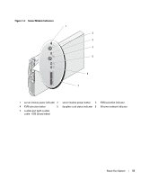
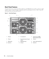
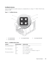
Back-Panel Features The back of the chassis supports four I/O module bays, the DRAC/MC, fan modules, and power supply modules. Figure 1-5 shows a sample configuration and the numbering for the bays. Table 1-4 provides information about the back-panel features. Figure 1-5. Back-Panel Features 1 2 3 4 12 11 5 6 4 3 10 1 I/O bay 2 4 I/O bay 1 7 KVM module 10 blanks (2) 7 2 1 8 9 2 fan modules (2) 5 Fibre Channel pass-through module 8 DRAC/MC module 11 I/O bay 4 3 PowerConnect 5316M Ethernet switch module 6 I/O bay 3 9 power supply modules (4) 12 blanks (2) 18 About Your System
-
 1
1 -
2
-
3
-
4
-
5
-
6
-
7
-
8
-
9
-
10
-
11
-
12
-
 13
13 -
 14
14 -
 15
15 -
 16
16 -
 17
17 -
 18
18 -
 19
19 -
 20
20 -
 21
21 -
 22
22 -
 23
23 -
24
-
25
-
26
-
27
-
28
-
29
-
30
-
31
-
32
-
33
-
34
-
35
-
36
-
37
-
38
-
39
-
40
-
41
-
42
-
43
-
44
-
45
-
46
-
47
-
48
-
49
-
50
-
51
-
52
-
53
-
54
-
55
-
56
-
57
-
58
-
59
-
60
-
61
-
62
-
63
-
64
-
65
-
66
-
67
-
68
-
69
-
70
-
71
-
72
-
73
-
74
-
75
-
76
-
77
-
78
-
79
-
80
-
81
-
82
-
83
-
84
-
85
-
86
-
87
-
88
-
89
-
90
-
91
-
92
-
93
-
94
-
95
-
96
-
97
-
98
-
99
-
100
-
101
-
102
-
103
-
104
-
105
-
106
-
107
-
108
-
109
-
110
-
111
-
112
-
113
-
114
-
115
-
116
-
117
-
118
-
119
-
120
-
121
-
122
-
123
-
124
-
125
-
126
-
127
-
128
-
129
-
130
-
131
-
132
-
133
-
134
-
135
-
136
-
137
-
138
-
139
-
140
-
141
-
142
-
143
-
144
-
145
-
146
-
147
-
148
-
149
-
150
-
151
-
152
-
153
-
154
-
155
-
156
-
157
-
158
-
159
-
160
 |
 |

18
About Your System
Back-Panel Features
The back of the chassis supports four I/O module bays, the DRAC/MC, fan modules, and power supply
modules. Figure 1-5 shows a sample configuration and the numbering for the bays. Table 1-4 provides
information about the back-panel features.
Figure 1-5.
Back-Panel Features
1
I/O bay 2
2
fan modules (2)
3
PowerConnect 5316M
Ethernet switch module
4
I/O bay 1
5
Fibre Channel pass-through
module
6
I/O bay 3
7
KVM module
8
DRAC/MC module
9
power supply modules (4)
10
blanks (2)
11
I/O bay 4
12
blanks (2)
9
2
3
6
10
7
8
4
1
5
12
11
3
4
1
2