Dell PowerEdge 1955 Hardware Owner's Manual (PDF) - Page 80
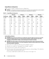
Sample Memory Configurations, Table 3-2 shows examples of supported memory configurations.
 |
View all Dell PowerEdge 1955 manuals
Add to My Manuals
Save this manual to your list of manuals |
Page 80 highlights
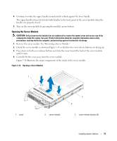
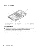
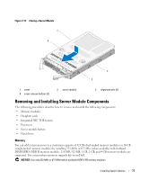
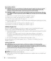
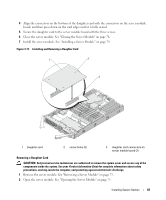
Sample Memory Configurations Table 3-2 shows examples of supported memory configurations. NOTICE: For configurations requiring less than eight memory modules, memory module blanks must be installed in four of the unoccupied memory sockets to maintain proper cooling airflow. See Table 3-2. Table 3-2. Sample Memory Configurations Total Memory 512 MB 1 GB 1 GB 2 GB 2 GB 4 GB 4 GB 8 GB 8 GB 16 GB 16 GB 32 GB Channel 0 DIMM 1 DIMM 5 256 MB blank 256 MB blank 512 MB blank 256 MB 256 MB 512 MB blank 1 GB blank 512 MB 512 MB 2 GB blank 1 GB 1 GB 4 GB blank 2 GB 2 GB 4 GB 4 GB Channel 1 DIMM 2 DIMM 6 256 MB blank 256 MB blank 512 MB blank 256 MB 256 MB 512 MB blank 1 GB blank 512 MB 512 MB 2 GB blank 1 GB 1 GB 4 GB blank 2 GB 2 GB 4 GB 4 GB Channel 2 DIMM 3 DIMM 7 none blank 256 MB blank none blank 256 MB 256 MB 512 MB blank 1 GB blank 512 MB 512 MB 2 GB blank 1 GB 1 GB 4 GB blank 2 GB 2 GB 4 GB 4 GB Channel 3 DIMM 4 DIMM 8 none blank 256 MB blank none blank 256 MB 256 MB 512 MB blank 1 GB blank 512 MB 512 MB 2 GB blank 1 GB 1 GB 4 GB blank 2 GB 2 GB 4 GB 4 GB Installing Memory Modules CAUTION: Only trained service technicians are authorized to remove the system cover and access any of the components inside the system. See your Product Information Guide for complete information about safety precautions, working inside the computer, and protecting against electrostatic discharge. CAUTION: The memory modules are hot to the touch for some time after the system has been powered down. Allow time for the memory modules to cool before handling them. Handle the memory modules by the card edges and avoid touching the components. 1 Remove the server module. See "Removing a Server Module" on page 73. 2 Open the server module. See "Opening the Server Module" on page 75. 3 Locate the memory module sockets. See Figure 6-3. 4 Press the ejectors on the memory module socket down and out, as shown in Figure 3-16, to allow the memory module to be inserted into the socket. I If a memory module blank is installed in the socket, remove it. See Figure 3-16. 80 Installing System Options
-
 1
1 -
2
-
3
-
4
-
5
-
6
-
7
-
8
-
9
-
10
-
11
-
12
-
13
-
14
-
15
-
16
-
17
-
18
-
19
-
20
-
21
-
22
-
23
-
24
-
25
-
26
-
27
-
28
-
29
-
30
-
31
-
32
-
33
-
34
-
35
-
36
-
37
-
38
-
39
-
40
-
41
-
42
-
43
-
44
-
45
-
46
-
47
-
48
-
49
-
50
-
51
-
52
-
53
-
54
-
55
-
56
-
57
-
58
-
59
-
60
-
61
-
62
-
63
-
64
-
65
-
66
-
67
-
68
-
69
-
70
-
71
-
72
-
73
-
74
-
 75
75 -
 76
76 -
 77
77 -
 78
78 -
 79
79 -
 80
80 -
 81
81 -
 82
82 -
 83
83 -
 84
84 -
 85
85 -
86
-
87
-
88
-
89
-
90
-
91
-
92
-
93
-
94
-
95
-
96
-
97
-
98
-
99
-
100
-
101
-
102
-
103
-
104
-
105
-
106
-
107
-
108
-
109
-
110
-
111
-
112
-
113
-
114
-
115
-
116
-
117
-
118
-
119
-
120
-
121
-
122
-
123
-
124
-
125
-
126
-
127
-
128
-
129
-
130
-
131
-
132
-
133
-
134
-
135
-
136
-
137
-
138
-
139
-
140
-
141
-
142
-
143
-
144
-
145
-
146
-
147
-
148
-
149
-
150
-
151
-
152
-
153
-
154
-
155
-
156
-
157
-
158
-
159
-
160
 |
 |