Dell PowerEdge 1955 Hardware Owner's Manual (PDF) - Page 16
Using USB Diskette or USB CD Drives, Hard-Drive Features - blades
 |
View all Dell PowerEdge 1955 manuals
Add to My Manuals
Save this manual to your list of manuals |
Page 16 highlights
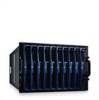
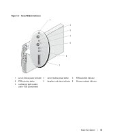
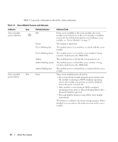
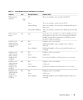
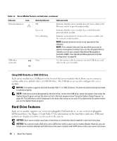
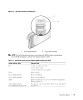
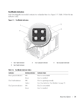
Table 1-2. Server Module Features and Indicators (continued) Indicator Icon Network indicators Activity Indicator Off Indicator Code Indicates that the server module does not have a link to the Ethernet switch or pass-through module. Green on Green blinking Indicates that the server module has a valid link to the network switch module. Indicates network activity between the server module and the network switch module. NOTE: External network activity is not reported by this indicator. NOTE: This network indicator may also blink green due to systems management activity if you use the integrated NIC to remotely access your system's Baseboard Management Controller (BMC). See "Baseboard Management Controller Configuration" on page 54. USB/video connector None Use the custom cable to connect external USB devices and video to the server module. Using USB Diskette or USB CD Drives Each server module has a USB port on the front of the server module which allows you to connect a custom cable for a diskette drive or USB CD drive. The USB drives are used to configure the server module. NOTICE: The system supports only Dell-branded USB 1.1 or USB 2.0 drives. The drive must be horizontal and level to operate properly. NOTE: If the drive must be designated as the boot drive, connect the USB drive, restart the system, then enter the System Setup Program and set the drive as first in the boot sequence (see "Using the System Setup Program" on page 43). The USB device will be displayed in the boot order setup screen only if it is attached to the system before you run the System Setup program. Hard-Drive Features Each server module supports one or two hot-pluggable SAS hard drives, or one or two hot-pluggable SATA hard drives. See Figure 1-4 and Table 1-3 for information on the hard-drive indicators. Different patterns are displayed as drive events occur in the system. NOTICE: Each server module must have a hard drive or a hard-drive blank installed in each hard-drive bay. NOTICE: You cannot install a SAS drive and a SATA drive within a given server module (blade). However, you can install server modules (blades) with SAS drives and server modules with SATA drives in the same server enclosure. 16 About Your System
-
 1
1 -
2
-
3
-
4
-
5
-
6
-
7
-
8
-
9
-
10
-
 11
11 -
 12
12 -
 13
13 -
 14
14 -
 15
15 -
 16
16 -
 17
17 -
 18
18 -
 19
19 -
 20
20 -
 21
21 -
22
-
23
-
24
-
25
-
26
-
27
-
28
-
29
-
30
-
31
-
32
-
33
-
34
-
35
-
36
-
37
-
38
-
39
-
40
-
41
-
42
-
43
-
44
-
45
-
46
-
47
-
48
-
49
-
50
-
51
-
52
-
53
-
54
-
55
-
56
-
57
-
58
-
59
-
60
-
61
-
62
-
63
-
64
-
65
-
66
-
67
-
68
-
69
-
70
-
71
-
72
-
73
-
74
-
75
-
76
-
77
-
78
-
79
-
80
-
81
-
82
-
83
-
84
-
85
-
86
-
87
-
88
-
89
-
90
-
91
-
92
-
93
-
94
-
95
-
96
-
97
-
98
-
99
-
100
-
101
-
102
-
103
-
104
-
105
-
106
-
107
-
108
-
109
-
110
-
111
-
112
-
113
-
114
-
115
-
116
-
117
-
118
-
119
-
120
-
121
-
122
-
123
-
124
-
125
-
126
-
127
-
128
-
129
-
130
-
131
-
132
-
133
-
134
-
135
-
136
-
137
-
138
-
139
-
140
-
141
-
142
-
143
-
144
-
145
-
146
-
147
-
148
-
149
-
150
-
151
-
152
-
153
-
154
-
155
-
156
-
157
-
158
-
159
-
160
 |
 |