Dell PowerEdge 1955 Hardware Owner's Manual (PDF) - Page 78
General Memory Module Installation Guidelines, Memory Sparing - total sockets
 |
View all Dell PowerEdge 1955 manuals
Add to My Manuals
Save this manual to your list of manuals |
Page 78 highlights
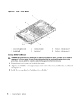
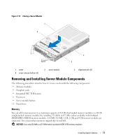
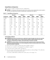
The eight memory module sockets are divided into two equal branches (0 and 1). Each branch consists of two channels: • Branch 0: Channel 0 (DIMM 1, DIMM 5) and channel 1 (DIMM 2, DIMM 6) • Branch 1: Channel 2 (DIMM 3, DIMM 7) and channel 3 (DIMM 4, DIMM 8) The first socket of each channel has white release tabs. The memory sockets are located on the system board at the back of the server module. See Figure 6-3 in "Server Module Board Connectors. General Memory Module Installation Guidelines • In memory configurations where sparing and mirroring are not supported, the memory modules must be installed in pairs of matched memory size, speed, technology, and vendor, beginning with Branch 0 (Channel 0 and Channel 1). • The system supports memory mirroring and memory sparing. (Only one of these features can be implemented at one time.) See"Memory Sparing" on page 78 and "Memory Mirroring" on page 79. • The system supports both single-ranked and dual-ranked memory modules. (Memory modules marked with a "1R" are single ranked and modules marked with a "2R" are dual ranked.) If you install both single-ranked and dual-ranked memory modules, the dual-ranked memory modules must be installed in Branch 1, regardless of capacity. NOTE: Dual-rank memory modules with less capacity take precedence over single-ranked memory modules with greater capacity. NOTICE: For configurations requiring less than eight memory modules, memory module blanks must be installed in four of the unoccupied memory sockets to maintain proper cooling airflow. See Table 3-2. Memory Sparing Memory sparing allocates four ranks of memory to a spare bank. These four ranks consist of the first rank of memory in sockets 1 through 4. • For single-rank memory modules, the entire capacity of the memory modules is allocated to sparing. • For dual-rank memory modules, only half of the total capacity is allocated to sparing. Table 3-1 shows how memory sparing divides the available and spared memory in each of the single- and dual-ranked memory module combinations. 78 Installing System Options
-
 1
1 -
2
-
3
-
4
-
5
-
6
-
7
-
8
-
9
-
10
-
11
-
12
-
13
-
14
-
15
-
16
-
17
-
18
-
19
-
20
-
21
-
22
-
23
-
24
-
25
-
26
-
27
-
28
-
29
-
30
-
31
-
32
-
33
-
34
-
35
-
36
-
37
-
38
-
39
-
40
-
41
-
42
-
43
-
44
-
45
-
46
-
47
-
48
-
49
-
50
-
51
-
52
-
53
-
54
-
55
-
56
-
57
-
58
-
59
-
60
-
61
-
62
-
63
-
64
-
65
-
66
-
67
-
68
-
69
-
70
-
71
-
72
-
 73
73 -
 74
74 -
 75
75 -
 76
76 -
 77
77 -
 78
78 -
 79
79 -
 80
80 -
 81
81 -
 82
82 -
 83
83 -
84
-
85
-
86
-
87
-
88
-
89
-
90
-
91
-
92
-
93
-
94
-
95
-
96
-
97
-
98
-
99
-
100
-
101
-
102
-
103
-
104
-
105
-
106
-
107
-
108
-
109
-
110
-
111
-
112
-
113
-
114
-
115
-
116
-
117
-
118
-
119
-
120
-
121
-
122
-
123
-
124
-
125
-
126
-
127
-
128
-
129
-
130
-
131
-
132
-
133
-
134
-
135
-
136
-
137
-
138
-
139
-
140
-
141
-
142
-
143
-
144
-
145
-
146
-
147
-
148
-
149
-
150
-
151
-
152
-
153
-
154
-
155
-
156
-
157
-
158
-
159
-
160
 |
 |