Epson C3500 Technical Reference Guide - Page 32
Attaching the Power Switch Cover
 |
View all Epson C3500 manuals
Add to My Manuals
Save this manual to your list of manuals |
Page 32 highlights
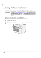
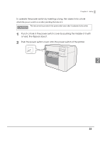
Attaching the Power Switch Cover Attaching the power switch cover prevents accidental pressing of the power switch. Before attaching the power switch cover, set DIP switch 1 to ON. (For details, see "Setting the DIP switches"Setting the DIP Switches on page 48.) The printer power can then be switched by turning the AC supply on and off, and you can also control the printer power with a device such as a distribution board. In this case, the power switch is used to reset the printer. To prevent the power switch from being pressed Attach the power switch cover as it is (without punching a hole in it). 1 Set DIP switch 1 to ON. 2 Push the power switch cover onto the power switch of the printer. 32
-
 1
1 -
2
-
3
-
4
-
5
-
6
-
7
-
8
-
9
-
10
-
11
-
12
-
13
-
14
-
15
-
16
-
17
-
18
-
19
-
20
-
21
-
22
-
23
-
24
-
25
-
26
-
 27
27 -
 28
28 -
 29
29 -
 30
30 -
 31
31 -
 32
32 -
 33
33 -
 34
34 -
 35
35 -
 36
36 -
 37
37 -
38
-
39
-
40
-
41
-
42
-
43
-
44
-
45
-
46
-
47
-
48
-
49
-
50
-
51
-
52
-
53
-
54
-
55
-
56
-
57
-
58
-
59
-
60
-
61
-
62
-
63
-
64
-
65
-
66
-
67
-
68
-
69
-
70
-
71
-
72
-
73
-
74
-
75
-
76
-
77
-
78
-
79
-
80
-
81
-
82
-
83
-
84
-
85
-
86
-
87
-
88
-
89
-
90
-
91
-
92
-
93
-
94
-
95
-
96
-
97
-
98
-
99
-
100
-
101
-
102
-
103
-
104
-
105
-
106
-
107
-
108
-
109
-
110
-
111
-
112
-
113
-
114
-
115
-
116
-
117
-
118
-
119
-
120
-
121
-
122
-
123
-
124
-
125
-
126
-
127
-
128
-
129
-
130
-
131
-
132
-
133
-
134
-
135
-
136
-
137
-
138
-
139
-
140
-
141
-
142
-
143
-
144
-
145
-
146
-
147
-
148
-
149
-
150
-
151
-
152
-
153
-
154
-
155
-
156
-
157
-
158
-
159
-
160
-
161
-
162
-
163
-
164
-
165
-
166
-
167
-
168
-
169
-
170
-
171
-
172
-
173
-
174
-
175
-
176
-
177
-
178
-
179
-
180
-
181
-
182
-
183
-
184
-
185
-
186
-
187
-
188
-
189
-
190
-
191
-
192
-
193
-
194
-
195
-
196
-
197
-
198
-
199
-
200
-
201
-
202
-
203
-
204
-
205
-
206
-
207
-
208
-
209
-
210
-
211
-
212
-
213
-
214
-
215
-
216
-
217
-
218
-
219
-
220
-
221
-
222
-
223
-
224
-
225
-
226
-
227
-
228
-
229
-
230
-
231
-
232
-
233
-
234
-
235
-
236
-
237
-
238
-
239
-
240
 |
 |

32
Attaching the Power Switch Cover
A
tt
ach
ing
t
he power sw
it
ch cover preve
nt
s acc
i
de
nt
al press
ing
of
t
he power sw
it
ch.
To prevent the power switch from being pressed
A
tt
ach
t
he power sw
it
ch cover as
it
i
s (w
it
ho
ut
p
un
ch
ing
a hole
in
it
).
1
Set DIP switch 1 to ON.
2
Push the power switch cover onto the power switch of the printer.
Before attaching the power switch cover, set DIP switch 1 to ON. (For details, see “Setting
the DIP switches”
Setting the DIP Switches on page 48
.) The printer power can then be
switched by turning the AC supply on and off, and you can also control the printer power
with a device such as a distribution board. In this case, the power switch is used to reset
the printer.