Epson NX User Manual - Page 73
Removing the LEDs
 |
View all Epson NX manuals
Add to My Manuals
Save this manual to your list of manuals |
Page 73 highlights
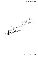
System Unit Removing the LEDs Follow these steps to remove the LEDs: 1 Remove the cover (see page 3-2) and any option cards that may be in the way (see page 3-5). 2 Disconnect the LED cables from CN15 and CN16 on the system board. 3 From the front of the chassis, press in on the right side of the LED unit and pull it forward to release it from the right chassis mounting hole. (See Figure 3-15.) 4 Continue bringing the right side of the LED unit forward and away from the front of the chassis until the left tab of the LED unit clears its mounting hole. Replacing the LEDs Follow these steps to replace the LED unit: 1 Ensure the LED wires are inserted through the LED access hole in the front of the chassis. Insert the left tab of the LED unit into its mounting bracket, then swing the right locking tab into its mounting hole. Ensure the LED wires are inserted through the LED access hole in the front of the chassis. 2 Rush the right locking tab through its hole in the front of the chassis. (See Figure 3-15.) 3 Connect the HDD LED cable to CN15 and the speed LED cable to CN 16. 4 Replace any option cards removed and the cover. 3-20 Epson NX Service Manual
-
 1
1 -
2
-
3
-
4
-
5
-
6
-
7
-
8
-
9
-
10
-
11
-
12
-
13
-
14
-
15
-
16
-
17
-
18
-
19
-
20
-
21
-
22
-
23
-
24
-
25
-
26
-
27
-
28
-
29
-
30
-
31
-
32
-
33
-
34
-
35
-
36
-
37
-
38
-
39
-
40
-
41
-
42
-
43
-
44
-
45
-
46
-
47
-
48
-
49
-
50
-
51
-
52
-
53
-
54
-
55
-
56
-
57
-
58
-
59
-
60
-
61
-
62
-
63
-
64
-
65
-
66
-
67
-
 68
68 -
 69
69 -
 70
70 -
 71
71 -
 72
72 -
 73
73 -
 74
74 -
 75
75 -
 76
76 -
 77
77 -
 78
78 -
79
-
80
-
81
-
82
-
83
-
84
-
85
-
86
-
87
-
88
-
89
-
90
-
91
-
92
-
93
-
94
-
95
-
96
-
97
-
98
-
99
-
100
-
101
-
102
-
103
-
104
-
105
-
106
-
107
-
108
-
109
-
110
-
111
-
112
-
113
-
114
-
115
-
116
-
117
-
118
-
119
-
120
-
121
-
122
-
123
-
124
-
125
-
126
-
127
-
128
-
129
-
130
-
131
-
132
-
133
-
134
-
135
-
136
-
137
-
138
-
139
-
140
-
141
-
142
-
143
-
144
-
145
-
146
-
147
-
148
-
149
-
150
-
151
-
152
-
153
-
154
 |
 |
