Fujitsu 5900C Operator's Guide - Page 23
Rear Side, Names And Functions Of Parts - vrs 4 5
 |
UPC - 097564306945
View all Fujitsu 5900C manuals
Add to My Manuals
Save this manual to your list of manuals |
Page 23 highlights
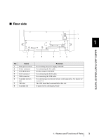
NAMES AND FUNCTIONS OF PARTS ■ Rear side 1 2 1 3 4 5 6 7 8 No. Name 1 Main power switch 2 Power connector 3 SCSI ID Switch 4 SCSI connector 5 USB connector 6 Extended memory slot 7 VRS slot 8 Extended slot Function For switching the power supply ON/OFF. For connecting the AC cable. Sets the scanner's SCSI ID. For connecting the SCSI cable. For connecting the USB cable. For connecting an extension memory (sold separately). For details see section 9.4. The VRS board has been installed in this slot. A spare slot for a third party board 1.1 Names and Functions of Parts 3
-
 1
1 -
2
-
3
-
4
-
5
-
6
-
7
-
8
-
9
-
10
-
11
-
12
-
13
-
14
-
15
-
16
-
17
-
 18
18 -
 19
19 -
 20
20 -
 21
21 -
 22
22 -
 23
23 -
 24
24 -
 25
25 -
 26
26 -
 27
27 -
 28
28 -
29
-
30
-
31
-
32
-
33
-
34
-
35
-
36
-
37
-
38
-
39
-
40
-
41
-
42
-
43
-
44
-
45
-
46
-
47
-
48
-
49
-
50
-
51
-
52
-
53
-
54
-
55
-
56
-
57
-
58
-
59
-
60
-
61
-
62
-
63
-
64
-
65
-
66
-
67
-
68
-
69
-
70
-
71
-
72
-
73
-
74
-
75
-
76
-
77
-
78
-
79
-
80
-
81
-
82
-
83
-
84
-
85
-
86
-
87
-
88
-
89
-
90
-
91
-
92
-
93
-
94
-
95
-
96
-
97
-
98
-
99
-
100
-
101
-
102
-
103
-
104
-
105
-
106
-
107
-
108
-
109
-
110
-
111
-
112
-
113
-
114
-
115
-
116
-
117
-
118
-
119
-
120
-
121
-
122
-
123
-
124
-
125
-
126
-
127
-
128
-
129
-
130
-
131
-
132
-
133
-
134
-
135
-
136
-
137
-
138
-
139
-
140
-
141
-
142
-
143
-
144
-
145
-
146
-
147
-
148
-
149
-
150
-
151
-
152
-
153
-
154
-
155
-
156
-
157
-
158
-
159
-
160
-
161
-
162
-
163
-
164
-
165
-
166
-
167
-
168
-
169
-
170
-
171
-
172
-
173
-
174
-
175
-
176
-
177
-
178
-
179
-
180
-
181
-
182
-
183
-
184
-
185
-
186
-
187
-
188
-
189
-
190
-
191
-
192
-
193
-
194
-
195
-
196
-
197
-
198
-
199
-
200
-
201
-
202
-
203
-
204
-
205
-
206
-
207
-
208
-
209
-
210
-
211
-
212
-
213
-
214
-
215
-
216
-
217
-
218
-
219
-
220
-
221
-
222
-
223
-
224
-
225
-
226
-
227
-
228
-
229
-
230
 |
 |

3
1.1 Names and Functions of Parts
1
NAMES AND FUNCTIONS OF PARTS
■
Rear side
No.
Name
Function
1
Main power switch
For switching the power supply ON/OFF.
2
Power connector
For connecting the AC cable.
3
SCSI ID Switch
Sets the scanner’s SCSI ID.
4
SCSI connector
For connecting the SCSI cable.
5
USB connector
For connecting the USB cable.
6
Extended memory
slot
For connecting an extension memory (sold separately). For details see
section 9.4
.
7
VRS slot
The VRS board has been installed in this slot.
8
Extended slot
A spare slot for a third party board
1
2
3
4
5
6
7
8