Gateway NV-53A Service Guide - Page 114
Secure the cap with the screws removed in, remove the screws securing it.
 |
View all Gateway NV-53A manuals
Add to My Manuals
Save this manual to your list of manuals |
Page 114 highlights
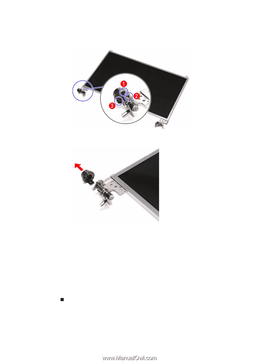
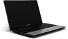
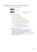
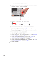
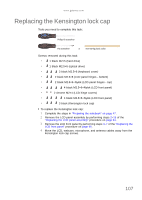
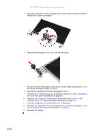
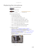
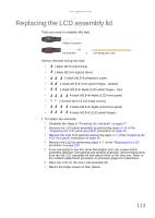
CHAPTER 3: Replacing notebook components 5 Note the orientation of the Kensington lock cap for later reference and then remove the screws securing it. 6 Detach the Kensington lock cap from the left hinge. 7 Position the new Kensington lock cap on the left hinge making sure it is in the same orientation noted on step 5. 8 Secure the cap with the screws removed in step 5. 9 Reinstall the LCD front panel by performing steps 8-11 of the "Replacing the LCD front panel" procedure on page 95. 10 Reinstall the LCD panel assembly by performing steps 16-23 of the "Replacing the LCD panel assembly" procedure on page 64. 11 Turn the notebook over so the palm rest is facing up. 12 Reinstall the keyboard and the keyboard cover by performing steps 5-8 of the "Replacing the keyboard" procedure on page 62. 13 Reinstall the battery. 108
-
 1
1 -
2
-
3
-
4
-
5
-
6
-
7
-
8
-
9
-
10
-
11
-
12
-
13
-
14
-
15
-
16
-
17
-
18
-
19
-
20
-
21
-
22
-
23
-
24
-
25
-
26
-
27
-
28
-
29
-
30
-
31
-
32
-
33
-
34
-
35
-
36
-
37
-
38
-
39
-
40
-
41
-
42
-
43
-
44
-
45
-
46
-
47
-
48
-
49
-
50
-
51
-
52
-
53
-
54
-
55
-
56
-
57
-
58
-
59
-
60
-
61
-
62
-
63
-
64
-
65
-
66
-
67
-
68
-
69
-
70
-
71
-
72
-
73
-
74
-
75
-
76
-
77
-
78
-
79
-
80
-
81
-
82
-
83
-
84
-
85
-
86
-
87
-
88
-
89
-
90
-
91
-
92
-
93
-
94
-
95
-
96
-
97
-
98
-
99
-
100
-
101
-
102
-
103
-
104
-
105
-
106
-
107
-
108
-
 109
109 -
 110
110 -
 111
111 -
 112
112 -
 113
113 -
 114
114 -
 115
115 -
 116
116 -
 117
117 -
 118
118 -
 119
119 -
120
-
121
-
122
-
123
-
124
-
125
-
126
-
127
-
128
-
129
-
130
-
131
-
132
-
133
-
134
-
135
-
136
-
137
-
138
-
139
-
140
-
141
-
142
-
143
-
144
-
145
-
146
-
147
-
148
-
149
-
150
-
151
-
152
-
153
-
154
-
155
-
156
-
157
-
158
-
159
-
160
-
161
-
162
-
163
-
164
-
165
-
166
-
167
-
168
 |
 |