Gateway NV-53A Service Guide - Page 82
Reinstall the palm rest by performing steps
 |
View all Gateway NV-53A manuals
Add to My Manuals
Save this manual to your list of manuals |
Page 82 highlights
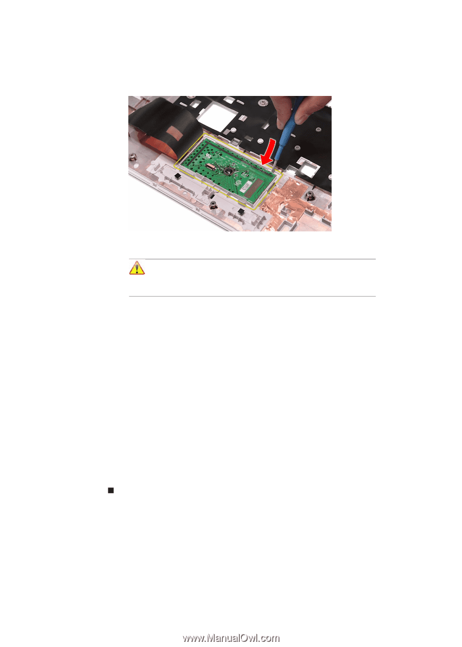
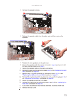
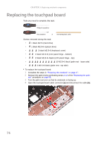
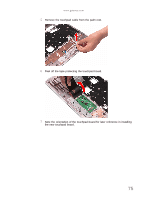
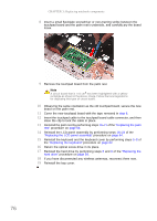
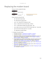
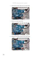
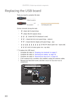
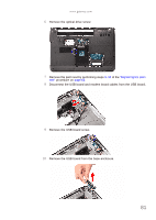
CHAPTER 3: Replacing notebook components 8 Insert a small flat-blade screwdriver or non-marring scribe between the touchpad board and the palm rest's underside, and carefully pry the board loose. 9 Remove the touchpad board from the palm rest. Note A circuit board that is >10 cm2 has been highlighted with a yellow rectangle as shown in the above image. Follow the local regulations for disposing this type of circuit board. 10 Observing the same orientation as the old touchpad board, secure the new board on the palm rest. 11 Cover the new touchpad board with the tape removed in step 6. 12 Insert the touchpad cable to the touchpad board cable connector, and then close the clip to lock the cable in place. 13 Reinstall the palm rest by performing steps 19-21 of the "Replacing the palm rest" procedure on page 68. 14 Reinstall the LCD panel assembly by performing steps 16-23 of the "Replacing the LCD panel assembly" procedure on page 64. 15 Reinstall the keyboard and the keyboard cover by performing steps 5-8 of the "Replacing the keyboard" procedure on page 62. 16 Return the optical screw drive in its place. 17 Reinstall the hard drive by performing steps 8 and 9 of the "Replacing the hard drive" procedure on page 54. 18 If you have disconnected any wireless antennas, reconnect them now. 19 Reinstall the bay cover. 76
-
 1
1 -
2
-
3
-
4
-
5
-
6
-
7
-
8
-
9
-
10
-
11
-
12
-
13
-
14
-
15
-
16
-
17
-
18
-
19
-
20
-
21
-
22
-
23
-
24
-
25
-
26
-
27
-
28
-
29
-
30
-
31
-
32
-
33
-
34
-
35
-
36
-
37
-
38
-
39
-
40
-
41
-
42
-
43
-
44
-
45
-
46
-
47
-
48
-
49
-
50
-
51
-
52
-
53
-
54
-
55
-
56
-
57
-
58
-
59
-
60
-
61
-
62
-
63
-
64
-
65
-
66
-
67
-
68
-
69
-
70
-
71
-
72
-
73
-
74
-
75
-
76
-
 77
77 -
 78
78 -
 79
79 -
 80
80 -
 81
81 -
 82
82 -
 83
83 -
 84
84 -
 85
85 -
 86
86 -
 87
87 -
88
-
89
-
90
-
91
-
92
-
93
-
94
-
95
-
96
-
97
-
98
-
99
-
100
-
101
-
102
-
103
-
104
-
105
-
106
-
107
-
108
-
109
-
110
-
111
-
112
-
113
-
114
-
115
-
116
-
117
-
118
-
119
-
120
-
121
-
122
-
123
-
124
-
125
-
126
-
127
-
128
-
129
-
130
-
131
-
132
-
133
-
134
-
135
-
136
-
137
-
138
-
139
-
140
-
141
-
142
-
143
-
144
-
145
-
146
-
147
-
148
-
149
-
150
-
151
-
152
-
153
-
154
-
155
-
156
-
157
-
158
-
159
-
160
-
161
-
162
-
163
-
164
-
165
-
166
-
167
-
168
 |
 |