Gateway NV-53A Service Guide - Page 94
Reinstall the LCD panel assembly by following the steps
 |
View all Gateway NV-53A manuals
Add to My Manuals
Save this manual to your list of manuals |
Page 94 highlights
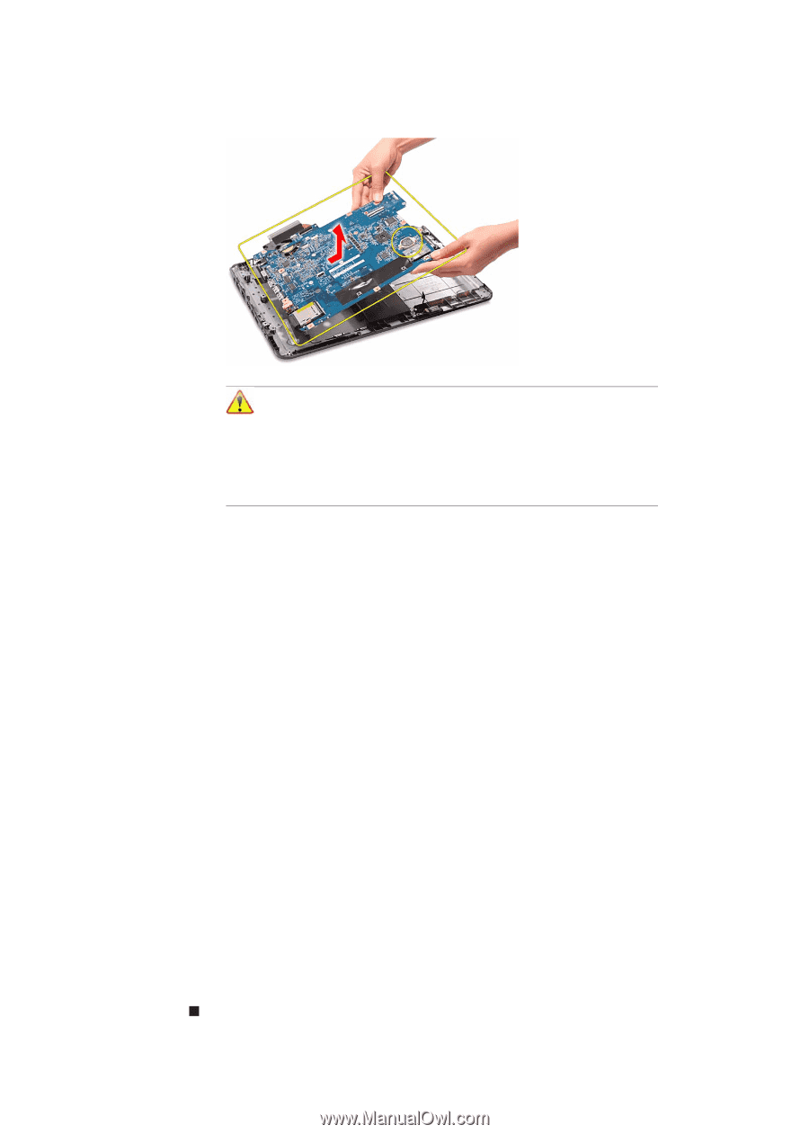
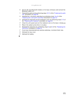
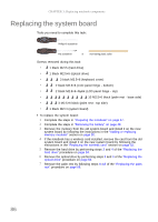
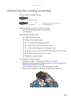
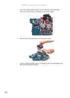
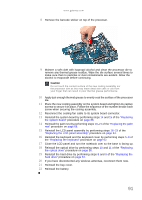
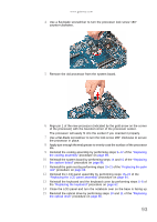
CHAPTER 3: Replacing notebook components 10 Carefully remove the system board from the base enclosure. 88 Note A circuit board that is >10 cm2 has been highlighted with a yellow rectangle as shown in the previous image. Follow the local regulations for disposing this type of circuit board. The RTC battery has been highlighted with a yellow circle in the previous image. Detach the RTC battery and follow the local regulations for disposing it. 11 Turn the system board over and remove the cooling assembly by performing steps 4-7 of the "Replacing the cooling assembly" procedure on page 89. 12 If your new system board does not include a processor, remove the processor from the old system board and install it on the new system board by performing steps 4-7 in the "Replacing the processor" section on page 92. 13 Reinstall the cooling assembly by performing steps 9-12 of the "Replacing the cooling assembly" procedure on page 89. 14 Place the new system board in the base enclosure and secure it with the screw removed in step 9. 15 Reconnect the USB board and Bluetooth module cables to their system board connectors; then reconnect the modem cable to the modem board. 16 Reinstall the palm rest by performing steps 19-21 of the "Replacing the palm rest" procedure on page 68. 17 Reinstall the LCD panel assembly by following the steps 16-23 of the "Replacing the LCD panel assembly" procedure on page 64. 18 Reinstall the keyboard and the keyboard cover by performing steps 5-8 of the "Replacing the keyboard" procedure on page 62. 19 Close the LCD panel and turn the notebook over so the base is facing up. 20 Reinstall the optical drive by performing steps 10 and 11 of the "Replacing the optical drive" procedure on page 56. 21 Reinstall the hard drive by performing steps 8 and 9 of the "Replacing the hard drive" procedure on page 54. 22 If you have disconnected any wireless antennas, reconnect them now. 23 Reinstall the bay cover. 24 Reinstall the battery.
-
 1
1 -
2
-
3
-
4
-
5
-
6
-
7
-
8
-
9
-
10
-
11
-
12
-
13
-
14
-
15
-
16
-
17
-
18
-
19
-
20
-
21
-
22
-
23
-
24
-
25
-
26
-
27
-
28
-
29
-
30
-
31
-
32
-
33
-
34
-
35
-
36
-
37
-
38
-
39
-
40
-
41
-
42
-
43
-
44
-
45
-
46
-
47
-
48
-
49
-
50
-
51
-
52
-
53
-
54
-
55
-
56
-
57
-
58
-
59
-
60
-
61
-
62
-
63
-
64
-
65
-
66
-
67
-
68
-
69
-
70
-
71
-
72
-
73
-
74
-
75
-
76
-
77
-
78
-
79
-
80
-
81
-
82
-
83
-
84
-
85
-
86
-
87
-
88
-
 89
89 -
 90
90 -
 91
91 -
 92
92 -
 93
93 -
 94
94 -
 95
95 -
 96
96 -
 97
97 -
 98
98 -
 99
99 -
100
-
101
-
102
-
103
-
104
-
105
-
106
-
107
-
108
-
109
-
110
-
111
-
112
-
113
-
114
-
115
-
116
-
117
-
118
-
119
-
120
-
121
-
122
-
123
-
124
-
125
-
126
-
127
-
128
-
129
-
130
-
131
-
132
-
133
-
134
-
135
-
136
-
137
-
138
-
139
-
140
-
141
-
142
-
143
-
144
-
145
-
146
-
147
-
148
-
149
-
150
-
151
-
152
-
153
-
154
-
155
-
156
-
157
-
158
-
159
-
160
-
161
-
162
-
163
-
164
-
165
-
166
-
167
-
168
 |
 |