Gateway NV-53A Service Guide - Page 72
Replacing notebook components, Remove the top hinge screws securing the LCD assembly.
 |
View all Gateway NV-53A manuals
Add to My Manuals
Save this manual to your list of manuals |
Page 72 highlights
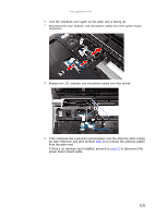
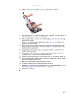
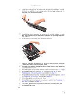
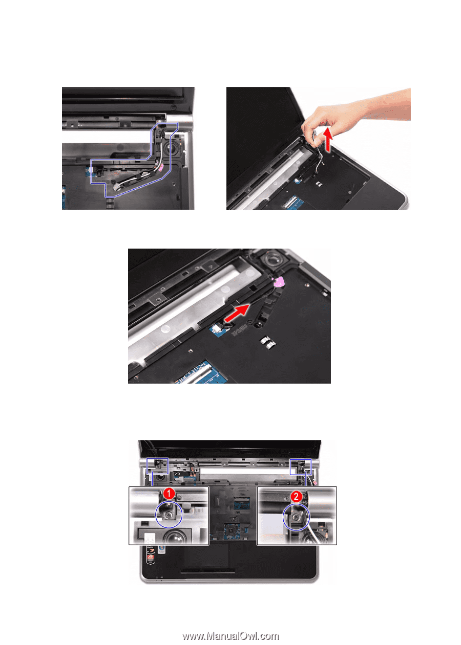
CHAPTER 3: Replacing notebook components 10 Release the antenna cables from their palm rest latches, and then pull them out from underneath the computer. 11 Disconnect the power button board cable from its system board connector, and then release it from its palm rest latches. 12 Carefully open the LCD panel to its fully extended position. 13 Move the LCD, webcam, and microphone cables away from the top hinge screws. 14 Remove the top hinge screws securing the LCD assembly. 66
-
 1
1 -
2
-
3
-
4
-
5
-
6
-
7
-
8
-
9
-
10
-
11
-
12
-
13
-
14
-
15
-
16
-
17
-
18
-
19
-
20
-
21
-
22
-
23
-
24
-
25
-
26
-
27
-
28
-
29
-
30
-
31
-
32
-
33
-
34
-
35
-
36
-
37
-
38
-
39
-
40
-
41
-
42
-
43
-
44
-
45
-
46
-
47
-
48
-
49
-
50
-
51
-
52
-
53
-
54
-
55
-
56
-
57
-
58
-
59
-
60
-
61
-
62
-
63
-
64
-
65
-
66
-
 67
67 -
 68
68 -
 69
69 -
 70
70 -
 71
71 -
 72
72 -
 73
73 -
 74
74 -
 75
75 -
 76
76 -
 77
77 -
78
-
79
-
80
-
81
-
82
-
83
-
84
-
85
-
86
-
87
-
88
-
89
-
90
-
91
-
92
-
93
-
94
-
95
-
96
-
97
-
98
-
99
-
100
-
101
-
102
-
103
-
104
-
105
-
106
-
107
-
108
-
109
-
110
-
111
-
112
-
113
-
114
-
115
-
116
-
117
-
118
-
119
-
120
-
121
-
122
-
123
-
124
-
125
-
126
-
127
-
128
-
129
-
130
-
131
-
132
-
133
-
134
-
135
-
136
-
137
-
138
-
139
-
140
-
141
-
142
-
143
-
144
-
145
-
146
-
147
-
148
-
149
-
150
-
151
-
152
-
153
-
154
-
155
-
156
-
157
-
158
-
159
-
160
-
161
-
162
-
163
-
164
-
165
-
166
-
167
-
168
 |
 |
CHAPTER 3: Replacing notebook components
66
10
Release the antenna cables from their palm rest latches, and then pull them
out
from underneath the computer
.
11
Disconnect the power button board cable from its system board connector, and then
release it from its palm rest latches.
12
Carefully open the LCD panel to its fully extended position.
13
Move the
LCD, webcam, and microphone cables away from the top hinge screws.
14
Remove the top hinge screws securing the LCD assembly.