Gateway NV-53A Service Guide - Page 99
Reinstall the system board by performing steps
 |
View all Gateway NV-53A manuals
Add to My Manuals
Save this manual to your list of manuals |
Page 99 highlights
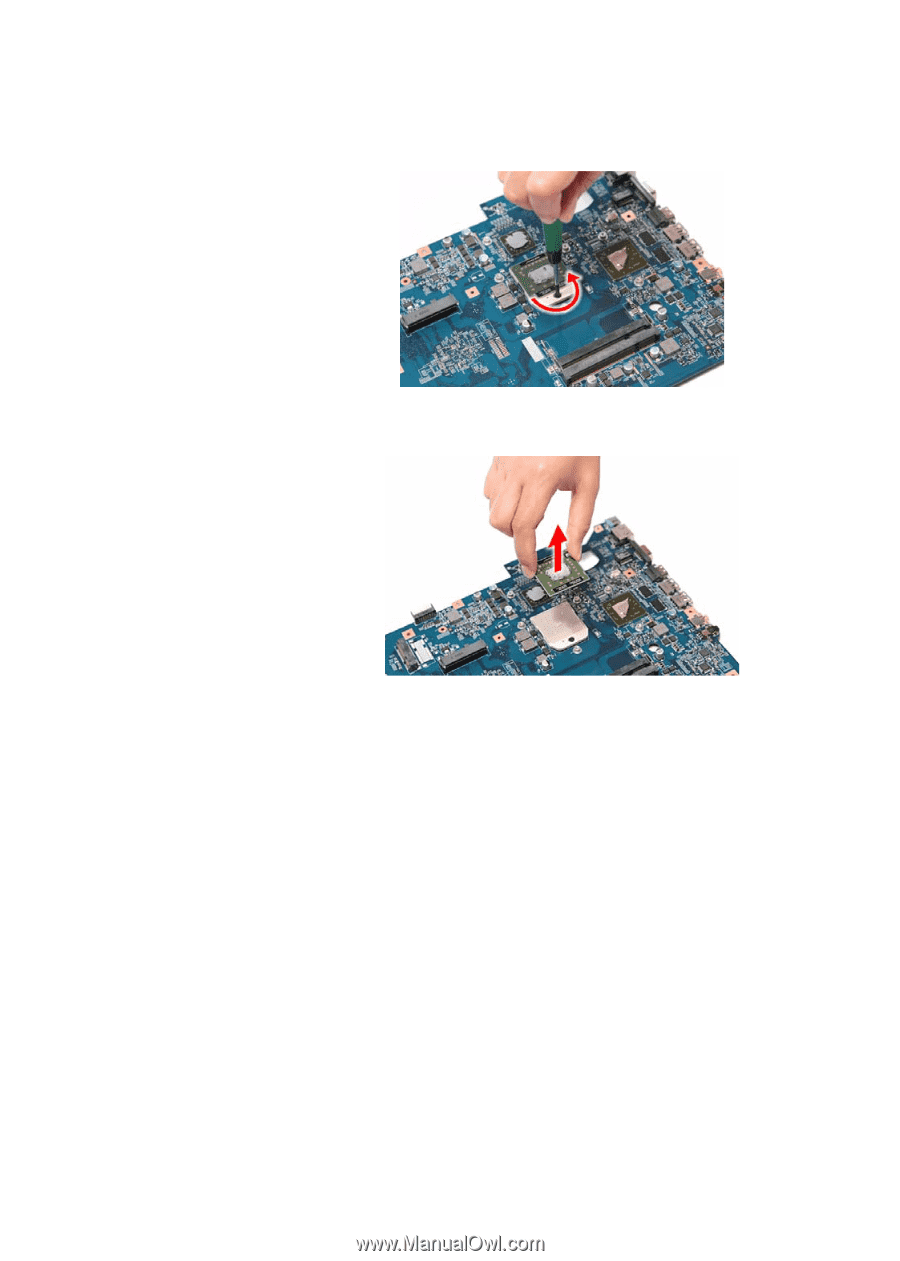
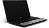
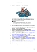
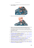
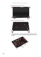
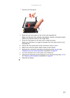
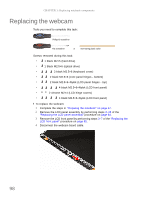
www.gateway.com 4 Use a flat-blade screwdriver to turn the processor lock screw 180° counter-clockwise. 5 Remove the old processor from the system board. 6 Align pin 1 of the new processor (indicated by the gold arrow on the corner of the processor) with the beveled corner of the processor socket. The processor will easily fit into the socket if you oriented it properly. 7 Use a flat-blade screwdriver to turn the lock screw 180° clockwise to secure the processor in place. 8 Apply just enough thermal grease to evenly coat the surface of the processor die. 9 Reinstall the cooling assembly by performing steps 9-12 of the "Replacing the cooling assembly" procedure on page 89. 10 Reinstall the system board by performing steps 14 and 15 of the "Replacing the system board" procedure on page 86. 11 Reinstall the palm rest by performing steps 19-21 of the "Replacing the palm rest" procedure on page 68. 12 Reinstall the LCD panel assembly by performing steps 16-23 of the "Replacing the LCD panel assembly" procedure on page 64. 13 Reinstall the keyboard and the keyboard cover by performing steps 5-8 of the "Replacing the keyboard" procedure on page 62. 14 Close the LCD panel and turn the notebook over so the base is facing up. 15 Reinstall the optical drive by performing steps 10 and 11 of the "Replacing the optical drive" procedure on page 56. 93
-
 1
1 -
2
-
3
-
4
-
5
-
6
-
7
-
8
-
9
-
10
-
11
-
12
-
13
-
14
-
15
-
16
-
17
-
18
-
19
-
20
-
21
-
22
-
23
-
24
-
25
-
26
-
27
-
28
-
29
-
30
-
31
-
32
-
33
-
34
-
35
-
36
-
37
-
38
-
39
-
40
-
41
-
42
-
43
-
44
-
45
-
46
-
47
-
48
-
49
-
50
-
51
-
52
-
53
-
54
-
55
-
56
-
57
-
58
-
59
-
60
-
61
-
62
-
63
-
64
-
65
-
66
-
67
-
68
-
69
-
70
-
71
-
72
-
73
-
74
-
75
-
76
-
77
-
78
-
79
-
80
-
81
-
82
-
83
-
84
-
85
-
86
-
87
-
88
-
89
-
90
-
91
-
92
-
93
-
 94
94 -
 95
95 -
 96
96 -
 97
97 -
 98
98 -
 99
99 -
 100
100 -
 101
101 -
 102
102 -
 103
103 -
 104
104 -
105
-
106
-
107
-
108
-
109
-
110
-
111
-
112
-
113
-
114
-
115
-
116
-
117
-
118
-
119
-
120
-
121
-
122
-
123
-
124
-
125
-
126
-
127
-
128
-
129
-
130
-
131
-
132
-
133
-
134
-
135
-
136
-
137
-
138
-
139
-
140
-
141
-
142
-
143
-
144
-
145
-
146
-
147
-
148
-
149
-
150
-
151
-
152
-
153
-
154
-
155
-
156
-
157
-
158
-
159
-
160
-
161
-
162
-
163
-
164
-
165
-
166
-
167
-
168
 |
 |