Gateway NV-53A Service Guide - Page 73
reconnect them to their system board connectors.
 |
View all Gateway NV-53A manuals
Add to My Manuals
Save this manual to your list of manuals |
Page 73 highlights
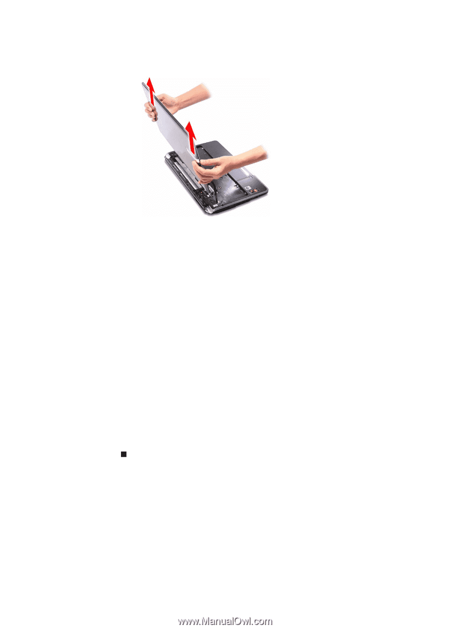
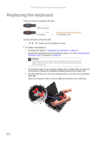
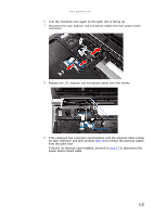
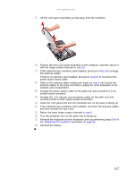
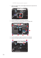
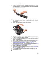
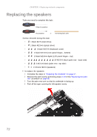
www.gateway.com 15 Lift the LCD panel assembly up and away from the notebook. 16 Position the new LCD panel assembly on the notebook, and then secure it with the hinge screws removed in step 14. 17 If the notebook has a wireless card installed, proceed to step 18 to arrange the antenna cables. If there's no wireless card installed, proceed to step 19 to reconnect the power button board cable. 18 Refer to the antenna cable routing note made on step 9 and secure the antenna cables to the palm rest before pulling the ends downward to the wireless card compartment. 19 Arrange the power button cable on the palm rest and reconnect it to its system board connector. 20 Arrange the LCD, webcam, and microphone cables on the palm rest and reconnect them to their system board connectors. 21 Close the LCD panel and turn the notebook over so the base is facing up. 22 If the notebook has a wireless card installed, reconnect the antenna cables and then reinstall the bay cover. 23 Return the base hinge screws removed in step 5. 24 Turn the notebook over so the palm rest is facing up. 25 Reinstall the keyboard and the keyboard cover by performing steps 5-8 of the "Replacing the keyboard" procedure on page 62. 26 Reinstall the battery. 67
-
 1
1 -
2
-
3
-
4
-
5
-
6
-
7
-
8
-
9
-
10
-
11
-
12
-
13
-
14
-
15
-
16
-
17
-
18
-
19
-
20
-
21
-
22
-
23
-
24
-
25
-
26
-
27
-
28
-
29
-
30
-
31
-
32
-
33
-
34
-
35
-
36
-
37
-
38
-
39
-
40
-
41
-
42
-
43
-
44
-
45
-
46
-
47
-
48
-
49
-
50
-
51
-
52
-
53
-
54
-
55
-
56
-
57
-
58
-
59
-
60
-
61
-
62
-
63
-
64
-
65
-
66
-
67
-
 68
68 -
 69
69 -
 70
70 -
 71
71 -
 72
72 -
 73
73 -
 74
74 -
 75
75 -
 76
76 -
 77
77 -
 78
78 -
79
-
80
-
81
-
82
-
83
-
84
-
85
-
86
-
87
-
88
-
89
-
90
-
91
-
92
-
93
-
94
-
95
-
96
-
97
-
98
-
99
-
100
-
101
-
102
-
103
-
104
-
105
-
106
-
107
-
108
-
109
-
110
-
111
-
112
-
113
-
114
-
115
-
116
-
117
-
118
-
119
-
120
-
121
-
122
-
123
-
124
-
125
-
126
-
127
-
128
-
129
-
130
-
131
-
132
-
133
-
134
-
135
-
136
-
137
-
138
-
139
-
140
-
141
-
142
-
143
-
144
-
145
-
146
-
147
-
148
-
149
-
150
-
151
-
152
-
153
-
154
-
155
-
156
-
157
-
158
-
159
-
160
-
161
-
162
-
163
-
164
-
165
-
166
-
167
-
168
 |
 |