Gateway NV-53A Service Guide - Page 97
Reinstall the keyboard and the keyboard cover by performing steps - battery 10 cell
 |
View all Gateway NV-53A manuals
Add to My Manuals
Save this manual to your list of manuals |
Page 97 highlights
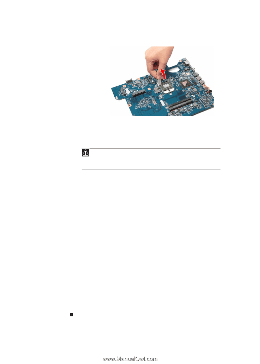
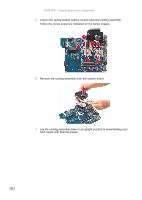
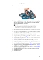
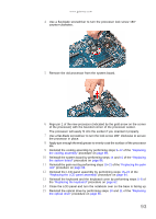
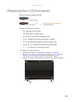
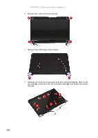
www.gateway.com 8 Remove the barcode sticker on top of the processor. 9 Moisten a soft cloth with isopropyl alcohol and clean the processor die to remove any thermal grease residue. Wipe the die surface several times to make sure that no particles or dust contaminants are evident. Allow the alcohol to evaporate before continuing. Caution Do not touch the contact surface of the new cooling assembly nor the processor dire as this may leave dead skin cells or oils from your finger that can result in poor thermal grease performance. 10 Apply just enough thermal grease to evenly coat the surface of the processor die. 11 Place the new cooling assembly on the system board and tighten its captive screws to secure it in place. Follow the sequence of the number beside each screw when securing the cooling assembly. 12 Reconnect the cooling fan cable to its system board connector. 13 Reinstall the system board by performing steps 14 and 15 of the "Replacing the system board" procedure on page 86. 14 Reinstall the palm rest by performing steps 19-21 of the "Replacing the palm rest" procedure on page 68. 15 Reinstall the LCD panel assembly by performing steps 16-23 of the "Replacing the LCD panel assembly" procedure on page 64. 16 Reinstall the keyboard and the keyboard cover by performing steps 5-8 of the "Replacing the keyboard" procedure on page 62. 17 Close the LCD panel and turn the notebook over so the base is facing up. 18 Reinstall the optical drive by performing steps 10 and 11 of the "Replacing the optical drive" procedure on page 56. 19 Reinstall the hard drive by performing steps 8 and 9 of the "Replacing the hard drive" procedure on page 54. 20 If you have disconnected any wireless antennas, reconnect them now. 21 Reinstall the bay cover. 22 Reinstall the battery. 91
-
 1
1 -
2
-
3
-
4
-
5
-
6
-
7
-
8
-
9
-
10
-
11
-
12
-
13
-
14
-
15
-
16
-
17
-
18
-
19
-
20
-
21
-
22
-
23
-
24
-
25
-
26
-
27
-
28
-
29
-
30
-
31
-
32
-
33
-
34
-
35
-
36
-
37
-
38
-
39
-
40
-
41
-
42
-
43
-
44
-
45
-
46
-
47
-
48
-
49
-
50
-
51
-
52
-
53
-
54
-
55
-
56
-
57
-
58
-
59
-
60
-
61
-
62
-
63
-
64
-
65
-
66
-
67
-
68
-
69
-
70
-
71
-
72
-
73
-
74
-
75
-
76
-
77
-
78
-
79
-
80
-
81
-
82
-
83
-
84
-
85
-
86
-
87
-
88
-
89
-
90
-
91
-
 92
92 -
 93
93 -
 94
94 -
 95
95 -
 96
96 -
 97
97 -
 98
98 -
 99
99 -
 100
100 -
 101
101 -
 102
102 -
103
-
104
-
105
-
106
-
107
-
108
-
109
-
110
-
111
-
112
-
113
-
114
-
115
-
116
-
117
-
118
-
119
-
120
-
121
-
122
-
123
-
124
-
125
-
126
-
127
-
128
-
129
-
130
-
131
-
132
-
133
-
134
-
135
-
136
-
137
-
138
-
139
-
140
-
141
-
142
-
143
-
144
-
145
-
146
-
147
-
148
-
149
-
150
-
151
-
152
-
153
-
154
-
155
-
156
-
157
-
158
-
159
-
160
-
161
-
162
-
163
-
164
-
165
-
166
-
167
-
168
 |
 |