Gateway NV-53A Service Guide - Page 88
Return the optical screw drive in its place.
 |
View all Gateway NV-53A manuals
Add to My Manuals
Save this manual to your list of manuals |
Page 88 highlights
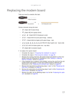
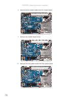
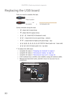
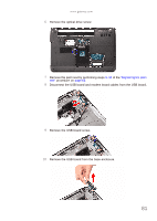
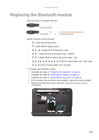
CHAPTER 3: Replacing notebook components 11 Place the new USB board in the base enclosure and secure it with the screw removed in step 9. 12 Connect the USB board and modem board cables to the new USB board. 13 Reinstall the palm rest by performing steps 19-21 of the "Replacing the palm rest" procedure on page 68. 14 Reinstall the LCD panel assembly by performing steps 16-23 of the "Replacing the LCD panel assembly" procedure on page 64. 15 Reinstall the keyboard and the keyboard cover by performing steps 5-8 of the "Replacing the keyboard" procedure on page 62. 16 Close the LCD panel and turn the notebook over so the base is facing up. 17 Return the optical screw drive in its place. 18 Reinstall the hard drive by performing steps 8 and 9 of the "Replacing the hard drive" procedure on page 54. 19 If you have disconnected any wireless antennas, reconnect them now. 20 Reinstall the bay cover. 21 Reinstall the battery. 82
-
 1
1 -
2
-
3
-
4
-
5
-
6
-
7
-
8
-
9
-
10
-
11
-
12
-
13
-
14
-
15
-
16
-
17
-
18
-
19
-
20
-
21
-
22
-
23
-
24
-
25
-
26
-
27
-
28
-
29
-
30
-
31
-
32
-
33
-
34
-
35
-
36
-
37
-
38
-
39
-
40
-
41
-
42
-
43
-
44
-
45
-
46
-
47
-
48
-
49
-
50
-
51
-
52
-
53
-
54
-
55
-
56
-
57
-
58
-
59
-
60
-
61
-
62
-
63
-
64
-
65
-
66
-
67
-
68
-
69
-
70
-
71
-
72
-
73
-
74
-
75
-
76
-
77
-
78
-
79
-
80
-
81
-
82
-
 83
83 -
 84
84 -
 85
85 -
 86
86 -
 87
87 -
 88
88 -
 89
89 -
 90
90 -
 91
91 -
 92
92 -
 93
93 -
94
-
95
-
96
-
97
-
98
-
99
-
100
-
101
-
102
-
103
-
104
-
105
-
106
-
107
-
108
-
109
-
110
-
111
-
112
-
113
-
114
-
115
-
116
-
117
-
118
-
119
-
120
-
121
-
122
-
123
-
124
-
125
-
126
-
127
-
128
-
129
-
130
-
131
-
132
-
133
-
134
-
135
-
136
-
137
-
138
-
139
-
140
-
141
-
142
-
143
-
144
-
145
-
146
-
147
-
148
-
149
-
150
-
151
-
152
-
153
-
154
-
155
-
156
-
157
-
158
-
159
-
160
-
161
-
162
-
163
-
164
-
165
-
166
-
167
-
168
 |
 |