HP Scitex FB10000 Site Preparation Guide Rev. 2 - Page 33
Positioning Peripheral Components
 |
View all HP Scitex FB10000 manuals
Add to My Manuals
Save this manual to your list of manuals |
Page 33 highlights
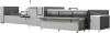
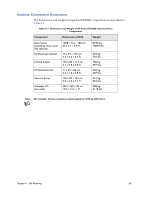
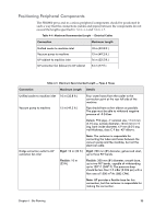
Positioning Peripheral Components The FB10000 press and its various peripheral components should be positioned in such a way that the connections (cables and pipes) between the components do not exceed the lengths specified in Table 4-4 and Table 4-5. Table 4-4 Maximum Recommended Length - Electrical Cables Connection Maximum Length Unified cooler to machine inlet Vacuum pump to machine UV cabinet to machine inlet UV extraction fan (blower) to UV cabinet 10 m (32.8 ft.) 15 m (49.2 ft.) 16 m (52.5 ft.) 24 m (77 ft.) Table 4-5 Maximum Recommended Length - Pipes & Hoses Connection Maximum Length Details Unified cooler to machine inlet 10 m (32.8 ft.) Vacuum pump to machine 15 m (49.2 ft.) Four water hoses from the cooler to the connection point at the rear left side of the machine. Pipe should have as few elbows as possible. The pipe must be able to withstand negative pressure of -0.24 bar. Details: PVC pipe, 4" nominal size, 114.3 mm (4.5") avg. outside diameter, 104.6 mm (4.1") avg. bore inside diameter, 4.9 mm (0.2") avg. wall thickness, class C 9 bar. 45º elbows. Bridge extraction outlet to UV extraction fan inlet Note: The customer is responsible for connecting the tubes and hoses between the vacuum pump and the machine, but not the electrical cable. Rigid: 10 m (33 ft.) Rigid: 200 mm (8") diameter, galvanized steel, up to three 90º bends. Flexible: 10 m (33 ft.) Flexible: 200 mm (8") diameter, smooth bore, up to two 90º bends, capable of withstanding up to 120º C (248º F). The pressure drop should be less than 2.5 mBar (0.036 psi) with a flow rate of 1500 m3/hr. (883 CFM). Note: HP provides a flexible hose for this connection, but the customer is responsible for making the connection. Chapter 4 - Site Planning 25
-
 1
1 -
2
-
3
-
4
-
5
-
6
-
7
-
8
-
9
-
10
-
11
-
12
-
13
-
14
-
15
-
16
-
17
-
18
-
19
-
20
-
21
-
22
-
23
-
24
-
25
-
26
-
27
-
 28
28 -
 29
29 -
 30
30 -
 31
31 -
 32
32 -
 33
33 -
 34
34 -
 35
35 -
 36
36 -
 37
37 -
 38
38 -
39
-
40
-
41
-
42
-
43
-
44
-
45
-
46
-
47
-
48
-
49
-
50
-
51
-
52
-
53
-
54
-
55
-
56
-
57
-
58
-
59
-
60
-
61
-
62
-
63
-
64
-
65
-
66
-
67
-
68
-
69
-
70
-
71
-
72
-
73
-
74
-
75
-
76
-
77
-
78
-
79
-
80
-
81
-
82
-
83
-
84
-
85
-
86
-
87
-
88
-
89
 |
 |
