HP Scitex FB10000 Site Preparation Guide Rev. 2 - Page 54
UV Extraction Fan, 7 ft., which is the length of the electrical cable that connects these two
 |
View all HP Scitex FB10000 manuals
Add to My Manuals
Save this manual to your list of manuals |
Page 54 highlights
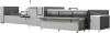
UV Extraction Fan Fumes produced during the ink curing process as well as ozone and heat produce by the UV lamp should be extracted from the production area, using an adequate extraction system. A UV extraction fan and silencer is supplied with the FB10000. The maximum distance between the UV extraction fan and the UV cabinet is 24 m (78.7 ft.), which is the length of the electrical cable that connects these two components. Table 4-17 describes the ducting that is required between the FB10000, the UV extraction fan, and the outside atmosphere (or the site's central extraction system). Table 4-17 Connections to UV Extraction Fan Connection Type Diameter Description From UV lamp to UV extraction fan inlet Rigid (galvanized steel) or flexible (smooth bore) 200 mm (8") From UV extraction fan outlet to outside atmosphere (or central extraction system) Galvanized steel 250 mm (10") Rigid: Maximum 10 m (33 ft.), up to three 90º bends Flexible: Maximum 10 m (33 ft.), up to two 90º bends, suitable for temperatures up to 120º C (248º F). 15 m (49 ft.), up to three 90º bends, terminated at least 5 m (16.4 ft.) above head height; provided by the customer Figure 4-16 Connecting UV Extraction Fan to Central Extraction System of Site (example) Note If the UV extraction fan is connected to the site's central extraction system, the system should operate at all times, otherwise it can affect the performance of the FB10000. 46 HP Scitex FB10000 Site Preparation Guide, Rev. 2
-
 1
1 -
2
-
3
-
4
-
5
-
6
-
7
-
8
-
9
-
10
-
11
-
12
-
13
-
14
-
15
-
16
-
17
-
18
-
19
-
20
-
21
-
22
-
23
-
24
-
25
-
26
-
27
-
28
-
29
-
30
-
31
-
32
-
33
-
34
-
35
-
36
-
37
-
38
-
39
-
40
-
41
-
42
-
43
-
44
-
45
-
46
-
47
-
48
-
 49
49 -
 50
50 -
 51
51 -
 52
52 -
 53
53 -
 54
54 -
 55
55 -
 56
56 -
 57
57 -
 58
58 -
 59
59 -
60
-
61
-
62
-
63
-
64
-
65
-
66
-
67
-
68
-
69
-
70
-
71
-
72
-
73
-
74
-
75
-
76
-
77
-
78
-
79
-
80
-
81
-
82
-
83
-
84
-
85
-
86
-
87
-
88
-
89
 |
 |
