HP Scitex FB10000 Site Preparation Guide Rev. 2 - Page 79
ft. straps to the eyebolts on the loader side of the chassis.
 |
View all HP Scitex FB10000 manuals
Add to My Manuals
Save this manual to your list of manuals |
Page 79 highlights
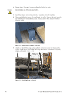
10 Attach 3 m (9.8 ft.) straps to the eyebolts on the loader side of the chassis. The straps should be inserted in the space between the panels on top of the loader, as shown in Figure 5-17. The straps should be connected with 2 shackles to the eyebolt and 1 shackle to the steel beam on its other side. Caution Figure 5-17 Straps Attached to Eyebolts on Loader Side Before lifting the machine with the crane, make sure that all four eyebolts are oriented towards the center of the machine and that the handles do not cross over the bolt, as shown in Figure 5-18. Machine front left side Figure 5-18 Orientation of Eyebolts when Lifting Machine (drawing is not to scale) Chapter 5 - Machine Delivery and Rigging 71
-
 1
1 -
2
-
3
-
4
-
5
-
6
-
7
-
8
-
9
-
10
-
11
-
12
-
13
-
14
-
15
-
16
-
17
-
18
-
19
-
20
-
21
-
22
-
23
-
24
-
25
-
26
-
27
-
28
-
29
-
30
-
31
-
32
-
33
-
34
-
35
-
36
-
37
-
38
-
39
-
40
-
41
-
42
-
43
-
44
-
45
-
46
-
47
-
48
-
49
-
50
-
51
-
52
-
53
-
54
-
55
-
56
-
57
-
58
-
59
-
60
-
61
-
62
-
63
-
64
-
65
-
66
-
67
-
68
-
69
-
70
-
71
-
72
-
73
-
 74
74 -
 75
75 -
 76
76 -
 77
77 -
 78
78 -
 79
79 -
 80
80 -
 81
81 -
 82
82 -
 83
83 -
 84
84 -
85
-
86
-
87
-
88
-
89
 |
 |

Chapter 5 - Machine Delivery and Rigging
71
10
Attach
3 m
(9.8 ft.) straps to the eyebolts on the loader side of the chassis. The
straps should be inserted in the space between the panels on top of the loader, as
shown in
Figure 5-17
.
The straps should be connected with
2
shackles to the eyebolt and 1 shackle to
the steel beam on its other side.
Figure 5-17
Straps Attached to Eyebolts on Loader Side
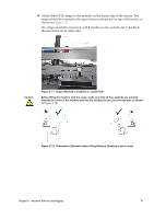
Caution
Before lifting the machine with the crane, make sure that all four eyebolts are oriented
towards the center of the machine and that the handles do not cross over the bolt, as shown
in
Figure 5-18
.
Figure 5-18
Orientation of Eyebolts when Lifting Machine (drawing is not to scale)
Machine front left side