HP Scitex FB10000 Site Preparation Guide Rev. 2 - Page 39
Electrical Diagram - 60 Hz/480V,
 |
View all HP Scitex FB10000 manuals
Add to My Manuals
Save this manual to your list of manuals |
Page 39 highlights
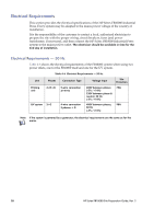
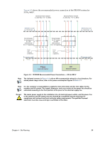
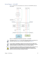
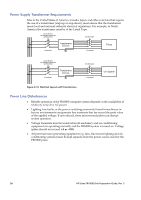
Electrical Diagram - 60 Hz/480V Figure 4-6 shows the recommended power connection of the FB10000 system for 60 Hz/480V. Electrical Power network 3 x 480 VAC + G, 60Hz L1 L2 L3 G Electrical Power network 3 x 480 VAC + G, 60Hz L1 L2 L3 G L1 L2 L3 L1 L2 L3 Transformer 55 KVA Primary - 3x480+G 60 Hz Delta Secondary 3x400+N+G Y Defined by Local Electrician Transformer Defined by Local Electrician L1 L2 L3 N Circuit breaker for printing unit 3 x 75A (75A thermal (In X 7 magnetic) L1 L2 L3 N L1 L2 L3 N Circuit breaker for UV system 3 x 80A (80A thermal (In X 10 magnetic) L1 L2 L3 N Power Line diameters 4 AWG/75ºC Customer site Press Power Line diameters 3 AWG/75ºC Customer site Press Press Electrical Cabinet UV Electrical Cabinet Figure 4-6 FB10000 Recommended Power Connections - 60 Hz/480 V Note The indicated currents in Figure 4-8 refer to HP-recommended ratings for circuit breakers. For actual power usage values, refer to the power consumption figures in Table 4-7. Note It is the customer's responsibility to supply the main inlet cable and the inlet cables for the machine and UV system. The length, diameters, and cross section of the power line should be calculated according to the final position of the press to the electrical supply line. Danger The mains power supply to the installation site, all electrical power outlets, and the power line to the machine and UV system must be checked by a qualified licensed electrician for compliance with national and local authority safety requirements. The qualified licensed electrician must also issue and sign a certificate to this effect. Chapter 4 - Site Planning 31
-
 1
1 -
2
-
3
-
4
-
5
-
6
-
7
-
8
-
9
-
10
-
11
-
12
-
13
-
14
-
15
-
16
-
17
-
18
-
19
-
20
-
21
-
22
-
23
-
24
-
25
-
26
-
27
-
28
-
29
-
30
-
31
-
32
-
33
-
 34
34 -
 35
35 -
 36
36 -
 37
37 -
 38
38 -
 39
39 -
 40
40 -
 41
41 -
 42
42 -
 43
43 -
 44
44 -
45
-
46
-
47
-
48
-
49
-
50
-
51
-
52
-
53
-
54
-
55
-
56
-
57
-
58
-
59
-
60
-
61
-
62
-
63
-
64
-
65
-
66
-
67
-
68
-
69
-
70
-
71
-
72
-
73
-
74
-
75
-
76
-
77
-
78
-
79
-
80
-
81
-
82
-
83
-
84
-
85
-
86
-
87
-
88
-
89
 |
 |
