HP d640 HP D640 High-Volume Printer - Installation Manual (Printer and Accesso - Page 109
Host Interface, Parallel Interface
 |
View all HP d640 manuals
Add to My Manuals
Save this manual to your list of manuals |
Page 109 highlights
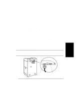
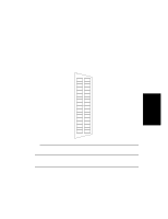
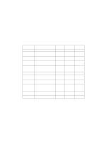
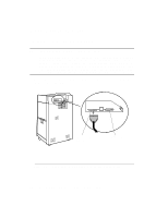
Host Interface Printer Interfaces Parallel Interface The parallel interface is accessible through a 36-pin connector at the back of the printer. The interface can be configured to operate in Institute of Electrical and Electronics Engineers (IEEE) 1284 mode. Signal names on the following connector pin assignment diagram (see Figure 3-2) relate to 1284 Compatible (Bitronics) mode. Busy Select Ack Fault P error Data 1 Data 2 Data 3 Data 4 Data 5 Data 6 Data 7 Data 8 Init Strobe Select in Auto Feed NC 1 19 2 20 3 21 4 22 5 23 6 24 7 25 8 26 9 27 10 28 11 29 12 30 13 31 14 32 15 33 16 34 17 35 18 36 Ground Ground Ground Ground Ground Ground Ground Ground Ground Ground Ground Ground Ground Ground Ground Ground Ground Peripheral logic hi Figure 3-2 Connector Pin Assignment NOTE: Not all IEEE 1284 parallel cables perform the same. For proper operation HP recommends that you only use the HP C2946A 3 meter cable (included) or the HP C2947A 10 meter cable (purchased separately). Host Computer Interface Installation and Configuration 3-7
-
 1
1 -
2
-
3
-
4
-
5
-
6
-
7
-
8
-
9
-
10
-
11
-
12
-
13
-
14
-
15
-
16
-
17
-
18
-
19
-
20
-
21
-
22
-
23
-
24
-
25
-
26
-
27
-
28
-
29
-
30
-
31
-
32
-
33
-
34
-
35
-
36
-
37
-
38
-
39
-
40
-
41
-
42
-
43
-
44
-
45
-
46
-
47
-
48
-
49
-
50
-
51
-
52
-
53
-
54
-
55
-
56
-
57
-
58
-
59
-
60
-
61
-
62
-
63
-
64
-
65
-
66
-
67
-
68
-
69
-
70
-
71
-
72
-
73
-
74
-
75
-
76
-
77
-
78
-
79
-
80
-
81
-
82
-
83
-
84
-
85
-
86
-
87
-
88
-
89
-
90
-
91
-
92
-
93
-
94
-
95
-
96
-
97
-
98
-
99
-
100
-
101
-
102
-
103
-
 104
104 -
 105
105 -
 106
106 -
 107
107 -
 108
108 -
 109
109 -
 110
110 -
 111
111 -
 112
112 -
 113
113 -
 114
114 -
115
-
116
-
117
-
118
-
119
-
120
-
121
-
122
-
123
-
124
-
125
-
126
-
127
-
128
-
129
-
130
-
131
-
132
-
133
-
134
-
135
-
136
-
137
-
138
-
139
-
140
-
141
-
142
-
143
-
144
-
145
-
146
-
147
-
148
-
149
-
150
-
151
-
152
-
153
-
154
-
155
-
156
-
157
-
158
-
159
-
160
-
161
-
162
-
163
-
164
-
165
-
166
-
167
-
168
-
169
-
170
-
171
-
172
-
173
-
174
-
175
-
176
-
177
-
178
-
179
-
180
-
181
-
182
-
183
-
184
-
185
-
186
-
187
-
188
-
189
-
190
-
191
-
192
-
193
-
194
-
195
-
196
-
197
-
198
-
199
-
200
-
201
-
202
-
203
-
204
-
205
-
206
-
207
-
208
-
209
-
210
 |
 |
