HP d640 HP D640 High-Volume Printer - Installation Manual (Printer and Accesso - Page 112
Procedure 1: Install the Interface Cable, Installation Instructions for C2946A or C2947A
 |
View all HP d640 manuals
Add to My Manuals
Save this manual to your list of manuals |
Page 112 highlights
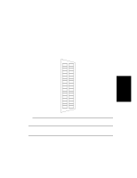
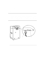
Procedure 1: Install the Interface Cable Procedure 1: Install the Interface Cable NOTE: Installation Instructions for C2946A or C2947A The "C" parallel connector (small end) of the cable has tabs located on both sides of the connector. To properly install the "C" connector, squeeze these tabs towards the center during cable installation. Squeezing the tabs as the connector is plugged into your printer, then releasing them will help ensure a good connection. Removal of the cable also requires that the tabs be squeezed in as the cable is disconnected. Connect the printer cable from the host to the Parallel or Serial connector on the back of the printer. See Figure 3-4. Parallel connector (type "C") Serial connector Figure 3-4 Connect the Printer Cable from the Host to the Printer 3-10 Host Computer Interface Installation and Configuration
-
 1
1 -
2
-
3
-
4
-
5
-
6
-
7
-
8
-
9
-
10
-
11
-
12
-
13
-
14
-
15
-
16
-
17
-
18
-
19
-
20
-
21
-
22
-
23
-
24
-
25
-
26
-
27
-
28
-
29
-
30
-
31
-
32
-
33
-
34
-
35
-
36
-
37
-
38
-
39
-
40
-
41
-
42
-
43
-
44
-
45
-
46
-
47
-
48
-
49
-
50
-
51
-
52
-
53
-
54
-
55
-
56
-
57
-
58
-
59
-
60
-
61
-
62
-
63
-
64
-
65
-
66
-
67
-
68
-
69
-
70
-
71
-
72
-
73
-
74
-
75
-
76
-
77
-
78
-
79
-
80
-
81
-
82
-
83
-
84
-
85
-
86
-
87
-
88
-
89
-
90
-
91
-
92
-
93
-
94
-
95
-
96
-
97
-
98
-
99
-
100
-
101
-
102
-
103
-
104
-
105
-
106
-
 107
107 -
 108
108 -
 109
109 -
 110
110 -
 111
111 -
 112
112 -
 113
113 -
 114
114 -
 115
115 -
 116
116 -
 117
117 -
118
-
119
-
120
-
121
-
122
-
123
-
124
-
125
-
126
-
127
-
128
-
129
-
130
-
131
-
132
-
133
-
134
-
135
-
136
-
137
-
138
-
139
-
140
-
141
-
142
-
143
-
144
-
145
-
146
-
147
-
148
-
149
-
150
-
151
-
152
-
153
-
154
-
155
-
156
-
157
-
158
-
159
-
160
-
161
-
162
-
163
-
164
-
165
-
166
-
167
-
168
-
169
-
170
-
171
-
172
-
173
-
174
-
175
-
176
-
177
-
178
-
179
-
180
-
181
-
182
-
183
-
184
-
185
-
186
-
187
-
188
-
189
-
190
-
191
-
192
-
193
-
194
-
195
-
196
-
197
-
198
-
199
-
200
-
201
-
202
-
203
-
204
-
205
-
206
-
207
-
208
-
209
-
210
 |
 |
