HP d640 HP D640 High-Volume Printer - Installation Manual (Printer and Accesso - Page 110
Serial Interface, Table 3-1, Pin Assignments for a Serial Cable lists RS-232C and RS-422A pin assign
 |
View all HP d640 manuals
Add to My Manuals
Save this manual to your list of manuals |
Page 110 highlights
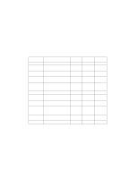
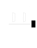
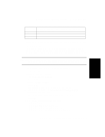
Printer Interfaces Serial Interface When you configure your printer for serial operation, you transfer data to the printer using serial communication protocol. You can use either an RS-232C or an RS-422A cable. Table 3-1, "Pin Assignments for a Serial Cable" lists RS-232C and RS-422A pin assignments and signal descriptions. Those pins not appearing in the table are not used. Figure 33 shows the RS-232 and RS-422A pinouts for the cable. Table 3-1 Pin Assignments for a Serial Cable Pin Number Description 1 2 3 3 (RS-422) 4 7 9 (RS-422) 10 (RS-422) 14 18 (RS-422) 20 Protective ground. Transmitted data (data from printer). Received data (received by printer). Received data inverted (RDA) (received by printer). Request to send. This signal is HIGH when unit is powered on. Signal ground. Send data inverted (SDA). Send data noninverted (SDB). Must be connected to ground (7) to select RS-422 mode (SDB). Receive data noninverted (RDB). Data terminal ready RS-232 * * * * * * RS-422 * * * * * * * I/O - Output Input Input Output Output Output Input Input Output The asterisks (*) identify signals used. The serial interface is accessible through a 25-pin female connector at the back of the printer. The interface can be configured to operate in an RS-232 or RS-422 configuration. Use the control panel to set the configuration. 3-8 Host Computer Interface Installation and Configuration
-
 1
1 -
2
-
3
-
4
-
5
-
6
-
7
-
8
-
9
-
10
-
11
-
12
-
13
-
14
-
15
-
16
-
17
-
18
-
19
-
20
-
21
-
22
-
23
-
24
-
25
-
26
-
27
-
28
-
29
-
30
-
31
-
32
-
33
-
34
-
35
-
36
-
37
-
38
-
39
-
40
-
41
-
42
-
43
-
44
-
45
-
46
-
47
-
48
-
49
-
50
-
51
-
52
-
53
-
54
-
55
-
56
-
57
-
58
-
59
-
60
-
61
-
62
-
63
-
64
-
65
-
66
-
67
-
68
-
69
-
70
-
71
-
72
-
73
-
74
-
75
-
76
-
77
-
78
-
79
-
80
-
81
-
82
-
83
-
84
-
85
-
86
-
87
-
88
-
89
-
90
-
91
-
92
-
93
-
94
-
95
-
96
-
97
-
98
-
99
-
100
-
101
-
102
-
103
-
104
-
 105
105 -
 106
106 -
 107
107 -
 108
108 -
 109
109 -
 110
110 -
 111
111 -
 112
112 -
 113
113 -
 114
114 -
 115
115 -
116
-
117
-
118
-
119
-
120
-
121
-
122
-
123
-
124
-
125
-
126
-
127
-
128
-
129
-
130
-
131
-
132
-
133
-
134
-
135
-
136
-
137
-
138
-
139
-
140
-
141
-
142
-
143
-
144
-
145
-
146
-
147
-
148
-
149
-
150
-
151
-
152
-
153
-
154
-
155
-
156
-
157
-
158
-
159
-
160
-
161
-
162
-
163
-
164
-
165
-
166
-
167
-
168
-
169
-
170
-
171
-
172
-
173
-
174
-
175
-
176
-
177
-
178
-
179
-
180
-
181
-
182
-
183
-
184
-
185
-
186
-
187
-
188
-
189
-
190
-
191
-
192
-
193
-
194
-
195
-
196
-
197
-
198
-
199
-
200
-
201
-
202
-
203
-
204
-
205
-
206
-
207
-
208
-
209
-
210
 |
 |
