HP d640 HP D640 High-Volume Printer - Installation Manual (Printer and Accesso - Page 30
Procedure 4: Getting To Know Your Printer
 |
View all HP d640 manuals
Add to My Manuals
Save this manual to your list of manuals |
Page 30 highlights
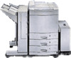
Installation Procedure 4: Getting To Know Your Printer Procedure 4: Getting To Know Your Printer Now that your printer is unpacked, familiarize yourself with the printer features and components. Figure 2-18, identifies the front and side view features of the printer. Control panel LCD Panel (64 x 240 dots) Power save indicator Standby switch ON Function buttons Display Contrast control Ejection unit Paper output tray Front cover Front door Tray1 Tray2 Tray3 Upper right cover Lower right cover Paper size indicators Paper level indicators Main power switch Figure 2-18 Printer Features, Front and Side View Installation 2-21
-
 1
1 -
2
-
3
-
4
-
5
-
6
-
7
-
8
-
9
-
10
-
11
-
12
-
13
-
14
-
15
-
16
-
17
-
18
-
19
-
20
-
21
-
22
-
23
-
24
-
 25
25 -
 26
26 -
 27
27 -
 28
28 -
 29
29 -
 30
30 -
 31
31 -
 32
32 -
 33
33 -
 34
34 -
 35
35 -
36
-
37
-
38
-
39
-
40
-
41
-
42
-
43
-
44
-
45
-
46
-
47
-
48
-
49
-
50
-
51
-
52
-
53
-
54
-
55
-
56
-
57
-
58
-
59
-
60
-
61
-
62
-
63
-
64
-
65
-
66
-
67
-
68
-
69
-
70
-
71
-
72
-
73
-
74
-
75
-
76
-
77
-
78
-
79
-
80
-
81
-
82
-
83
-
84
-
85
-
86
-
87
-
88
-
89
-
90
-
91
-
92
-
93
-
94
-
95
-
96
-
97
-
98
-
99
-
100
-
101
-
102
-
103
-
104
-
105
-
106
-
107
-
108
-
109
-
110
-
111
-
112
-
113
-
114
-
115
-
116
-
117
-
118
-
119
-
120
-
121
-
122
-
123
-
124
-
125
-
126
-
127
-
128
-
129
-
130
-
131
-
132
-
133
-
134
-
135
-
136
-
137
-
138
-
139
-
140
-
141
-
142
-
143
-
144
-
145
-
146
-
147
-
148
-
149
-
150
-
151
-
152
-
153
-
154
-
155
-
156
-
157
-
158
-
159
-
160
-
161
-
162
-
163
-
164
-
165
-
166
-
167
-
168
-
169
-
170
-
171
-
172
-
173
-
174
-
175
-
176
-
177
-
178
-
179
-
180
-
181
-
182
-
183
-
184
-
185
-
186
-
187
-
188
-
189
-
190
-
191
-
192
-
193
-
194
-
195
-
196
-
197
-
198
-
199
-
200
-
201
-
202
-
203
-
204
-
205
-
206
-
207
-
208
-
209
-
210
 |
 |

Procedure 4: Getting To Know Your Printer
Installation
2-21
Installation
Procedure
4: Getting To Know Your Printer
Now that your printer is unpacked, familiarize yourself with the printer features and com-
ponents. Figure 2-18, identifies the front and side view features of the printer.
Figure 2-18
Printer Features, Front and Side View
..
..
....
.
.
.
.
.
.....
Paper output tray
Ejection unit
Control panel
Upper right cover
Lower right cover
Main power switch
Paper level indicators
Paper size indicators
Front cover
Front door
Tray1
Tray2
Tray3
.
.
.
.
.
.
.
.
.
.
.
.
.
.
.
.
.
.
Power save indicator
Display
Contrast control
Function
buttons
LCD Panel (64 x 240 dots)
Standby switch
ON