Lantronix EMG 8500 EMG User Guide - Page 55
Physical Installation, EQUIPMENT, IS FOR INDOOR USE
 |
View all Lantronix EMG 8500 manuals
Add to My Manuals
Save this manual to your list of manuals |
Page 55 highlights
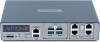
4: EMG 7500 Installation Component (continued) Temperature Relative Humidity Front USB Port Rear Memory Card LED Indicators Operating Atmosphere Caution: EQUIPMENT IS FOR INDOOR USE ONLY! Description Operating: 0 to 50°C (32 to 122°F) Storage: -20 to 80°C (-4 to 176°F) Operating: 10% to 90% non-condensing Storage: 10% to 90% non-condensing (1) port, type A, host USB 2.0 (HS, FS, LS) for use with flash drive (1) Secure Digital (micro SD) memory card slot supporting: SD SDHC Ethernet port (upper LED on front panel) Connectivity (lower LED on front panel) For use at altitudes no more than 2000 meters above sea level only. For use in non-tropical conditions only. Physical Installation The EMG module uses convection cooling to dissipate excess heat. To install the EMG unit: 1. Mount the EMG unit. If free-standing, attach the adhesive-backed rubber feet to the base of the EMG unit. Place the unit securely on a desktop or other flat horizontal surface. If rack-mounted, mount the unit securely in a 19-inch rack. See Rack Mount Installation (on page 56). If wall-mounted, mount the unit securely on a flat vertical surface. Wall Mount Installation (on page 57). 2. Connect the serial device(s) to the EMG unit's device ports. See Connecting to a Device Port (on page 58). 3. Choose one of the following options: To configure the EMG using the network, or to monitor serial devices on the network, connect at least one EMG network port to a network. See Connecting to Network Ports (on page 60). To configure the EMG unit using a dumb terminal or a computer with terminal emulation, connect the terminal or PC to the front panel EMG console port. See Connecting Terminals (on page 60). 4. Connect the power cord to power on the unit. See Power Input (on page 61). 5. Wait approximately one minute for the boot process to complete. The first time the EMG boots, it attempts to get an IP address from DHCP. To configure the network settings, see Chapter 5: Quick Setup. EMG™ Edge Management Gateway User Guide 55
-
 1
1 -
2
-
3
-
4
-
5
-
6
-
7
-
8
-
9
-
10
-
11
-
12
-
13
-
14
-
15
-
16
-
17
-
18
-
19
-
20
-
21
-
22
-
23
-
24
-
25
-
26
-
27
-
28
-
29
-
30
-
31
-
32
-
33
-
34
-
35
-
36
-
37
-
38
-
39
-
40
-
41
-
42
-
43
-
44
-
45
-
46
-
47
-
48
-
49
-
 50
50 -
 51
51 -
 52
52 -
 53
53 -
 54
54 -
 55
55 -
 56
56 -
 57
57 -
 58
58 -
 59
59 -
 60
60 -
61
-
62
-
63
-
64
-
65
-
66
-
67
-
68
-
69
-
70
-
71
-
72
-
73
-
74
-
75
-
76
-
77
-
78
-
79
-
80
-
81
-
82
-
83
-
84
-
85
-
86
-
87
-
88
-
89
-
90
-
91
-
92
-
93
-
94
-
95
-
96
-
97
-
98
-
99
-
100
-
101
-
102
-
103
-
104
-
105
-
106
-
107
-
108
-
109
-
110
-
111
-
112
-
113
-
114
-
115
-
116
-
117
-
118
-
119
-
120
-
121
-
122
-
123
-
124
-
125
-
126
-
127
-
128
-
129
-
130
-
131
-
132
-
133
-
134
-
135
-
136
-
137
-
138
-
139
-
140
-
141
-
142
-
143
-
144
-
145
-
146
-
147
-
148
-
149
-
150
-
151
-
152
-
153
-
154
-
155
-
156
-
157
-
158
-
159
-
160
-
161
-
162
-
163
-
164
-
165
-
166
-
167
-
168
-
169
-
170
-
171
-
172
-
173
-
174
-
175
-
176
-
177
-
178
-
179
-
180
-
181
-
182
-
183
-
184
-
185
-
186
-
187
-
188
-
189
-
190
-
191
-
192
-
193
-
194
-
195
-
196
-
197
-
198
-
199
-
200
-
201
-
202
-
203
-
204
-
205
-
206
-
207
-
208
-
209
-
210
-
211
-
212
-
213
-
214
-
215
-
216
-
217
-
218
-
219
-
220
-
221
-
222
-
223
-
224
-
225
-
226
-
227
-
228
-
229
-
230
-
231
-
232
-
233
-
234
-
235
-
236
-
237
-
238
-
239
-
240
-
241
-
242
-
243
-
244
-
245
-
246
-
247
-
248
-
249
-
250
-
251
-
252
-
253
-
254
-
255
-
256
-
257
-
258
-
259
-
260
-
261
-
262
-
263
-
264
-
265
-
266
-
267
-
268
-
269
-
270
-
271
-
272
-
273
-
274
-
275
-
276
-
277
-
278
-
279
-
280
-
281
-
282
-
283
-
284
-
285
-
286
-
287
-
288
-
289
-
290
-
291
-
292
-
293
-
294
-
295
-
296
-
297
-
298
-
299
-
300
-
301
-
302
-
303
-
304
-
305
-
306
-
307
-
308
-
309
-
310
-
311
-
312
-
313
-
314
-
315
-
316
-
317
-
318
-
319
-
320
-
321
-
322
-
323
-
324
-
325
-
326
-
327
-
328
-
329
-
330
-
331
-
332
-
333
-
334
-
335
-
336
-
337
-
338
-
339
-
340
-
341
-
342
-
343
-
344
-
345
-
346
-
347
-
348
-
349
-
350
-
351
-
352
-
353
-
354
-
355
-
356
-
357
-
358
-
359
-
360
-
361
-
362
-
363
-
364
-
365
-
366
-
367
-
368
-
369
-
370
-
371
-
372
-
373
-
374
-
375
-
376
-
377
-
378
-
379
-
380
-
381
-
382
-
383
-
384
-
385
-
386
-
387
-
388
-
389
-
390
-
391
-
392
-
393
-
394
-
395
-
396
-
397
-
398
-
399
-
400
-
401
-
402
-
403
-
404
-
405
-
406
-
407
-
408
-
409
-
410
-
411
-
412
-
413
-
414
-
415
-
416
-
417
-
418
-
419
-
420
-
421
-
422
-
423
-
424
-
425
-
426
-
427
-
428
-
429
-
430
-
431
-
432
-
433
-
434
-
435
-
436
-
437
-
438
-
439
-
440
-
441
-
442
-
443
-
444
-
445
-
446
-
447
-
448
-
449
-
450
-
451
-
452
-
453
-
454
-
455
-
456
-
457
-
458
-
459
-
460
-
461
-
462
-
463
-
464
-
465
-
466
-
467
-
468
-
469
-
470
-
471
-
472
-
473
-
474
-
475
-
476
-
477
-
478
-
479
-
480
-
481
-
482
-
483
-
484
-
485
-
486
-
487
-
488
-
489
-
490
-
491
-
492
-
493
-
494
-
495
 |
 |
