Panasonic AW-HE130 Operating Instructions - Page 19
Parts and their functions continued, G/L IN connector <G/L IN> - wall mount
 |
View all Panasonic AW-HE130 manuals
Add to My Manuals
Save this manual to your list of manuals |
Page 19 highlights
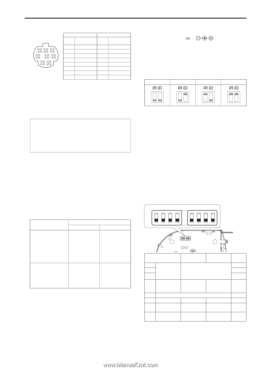
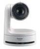
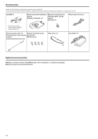
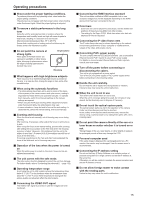
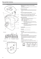
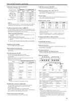
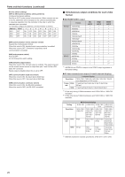
Parts and their functions (continued) 10.RS-232C connectors Connects to an RS-232C cable. RS-232C IN/OUT connector appearance 8 7 6 5 4 3 2 1 Mini Din 8-pin (JST) RS-232C IN Pin No. Signal 1 DTR_IN 2 DSR_IN 3 TXD_IN 4 GND 5 RXD_IN 6 GND 7 IR OUT R 8 IR OUT L RS-232C OUT Pin No. Signal 1 DTR_OUT 2 DSR_OUT 3 TXD_OUT 4 GND 5 RXD_OUT 6 GND 7 NC 8 NC • Be aware that the polarities (+/-) of the serial data may be different depending on the specifications of the device to be connected. 11.LAN connector for IP control This LAN connector (RJ45) is connected when exercising IP control over the unit from an external device. Use a cable with the following specifications for the connection to this connector. When using a PoE+ Ethernet hub LAN cable*1 (category 5e or above, straight cable), max. 100 m [3280 ft] When not using a PoE+ Ethernet hub LAN cable*1 (category 5 or above, straight cable), max. 100 m [3280 ft] *1 Use of an STP (shielded twisted pair) cable is recommended. 12.HDMI connector [HDMI] This is the HDMI video output connector. 13.Anti-theft wire mounting hole The anti-theft wire bracket (available from a hardware store) is attached here. 14.G/L IN connector This is the external sync signal input connector. This unit supports BBS (Black Burst Sync) and tri-level synchronization. Supply to this connector the signals that correspond to the video signal format which has been set. Format 1080/59.94p 1080/29.97p 1080/23.98p 1080/59.94i 1080/29.97PsF 1080/23.98PsF 720/59.94p 480/59.94p(i) 1080/50p 1080/25p 1080/50i 1080/25PsF 720/50p 576/50p(i) External sync signal input format BBS Tri-level sync 480/59.94i 1080/59.94i 480/59.94i 1080/59.94i 480/59.94i 480/59.94i 576/50i 576/50i 576/50i 576/50i 720/59.94p - 1080/50i 1080/50i 720/50p ― • Locking to a subcarrier is not possible with BBS. 15.VIDEO OUT connector This is the output connector used for monitoring the camera's composite video signals. Use the monitor in the internal synchronization mode. Provide a BNC coaxial cable as the connecting cable. There is a delay in the VIDEO OUT signal output by 120H (HD lines) when at 720p and at 90H (HD lines) for any other. 16.Hole used to secure cable cover Use the screw provided to secure the cable cover. 17.SDI OUT connector This is the SDI video signal output connector. 18.DC IN connector Connect the AC adaptor supplied with the unit to this connector to supply the DC 12 V voltage to the unit. 19.Cable clamp This is used to hold the cable connection to the DC IN connector and prevent it from becoming disconnected. 20.IR ID switches CAM1 CAM2 CAM3 CAM4 These are used to select the ID of the wireless remote control (optional accessory). The IR ID switch settings "CAM1" to "CAM4" correspond to the to buttons on the wireless remote control. 21.Square holes (X2) for cable cover tabs The tabs on the two sides of the cable cover are fitted into these holes. 22. connector Inputs external audio (microphone, line). 23.Ground connector Connects to the ground connector on a wall outlet, ground bar, etc. for grounding. (→ page @@) 24.Tripod screw holes (Screw: 1/4-20 UNC, ISO 1222 (6.35 mm)) Use these screw holes when securing the unit to a tripod, etc. 25.Service switches SW1 SW2 SW3 SW4 ON OFF SW5 SW6 SW7 SW8 Function OFF ON SW1 SW2 SW3 SW4 SW5 SW6 SW7 SW8 Camera address setting (standard serial communication) See descriptions for SW1 to SW3 Communication format Panasonic Standard serial proprietary serial communication communication Always leave at OFF (used for factory adjustments) Infrared output Disable Enable Communication 9600 bps baud rate 38400 bps Communication RS-422 connector RS-232C Factory settings OFF OFF OFF OFF OFF OFF OFF OFF • Perform switch settings before turning the unit on. • Cameras whose camera address setting switches are set to AUTO cannot coexist with cameras whose switches are set to 1 to 7. • Manually setting multiple cameras to the same address will not allow you to control multiple cameras from a single controller simultaneously. 19
-
 1
1 -
2
-
3
-
4
-
5
-
6
-
7
-
8
-
9
-
10
-
11
-
12
-
13
-
 14
14 -
 15
15 -
 16
16 -
 17
17 -
 18
18 -
 19
19 -
 20
20 -
 21
21 -
 22
22 -
 23
23 -
 24
24 -
25
-
26
-
27
-
28
-
29
-
30
-
31
-
32
-
33
-
34
-
35
-
36
-
37
-
38
-
39
-
40
-
41
-
42
-
43
-
44
-
45
-
46
-
47
-
48
-
49
-
50
-
51
-
52
-
53
-
54
-
55
-
56
-
57
-
58
-
59
-
60
-
61
-
62
-
63
-
64
-
65
-
66
-
67
-
68
-
69
-
70
-
71
-
72
-
73
-
74
-
75
-
76
-
77
-
78
-
79
-
80
-
81
-
82
-
83
-
84
-
85
-
86
-
87
-
88
-
89
-
90
-
91
-
92
-
93
-
94
-
95
-
96
-
97
-
98
-
99
-
100
-
101
-
102
-
103
-
104
-
105
-
106
-
107
-
108
-
109
-
110
-
111
-
112
-
113
-
114
-
115
-
116
-
117
-
118
-
119
-
120
-
121
-
122
-
123
-
124
-
125
-
126
 |
 |