Panasonic AW-HE130 Operating Instructions - Page 86
Multi-Screen setup screen, Digital Extender, OSD Mix, SDI Out, Video Out, OSD Status, Model Select
 |
View all Panasonic AW-HE130 manuals
Add to My Manuals
Save this manual to your list of manuals |
Page 86 highlights
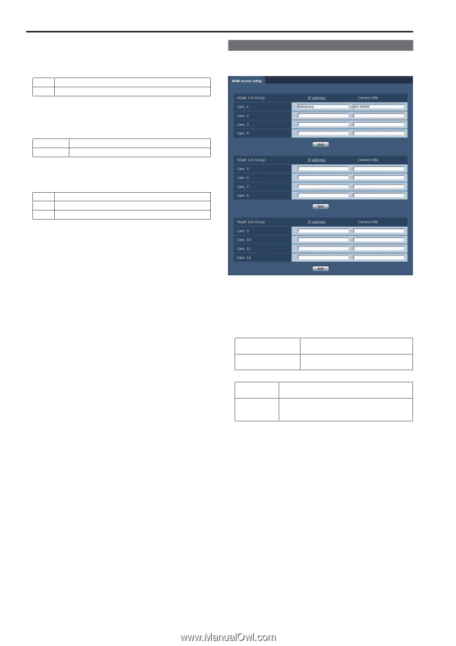
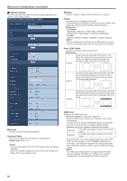
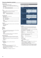
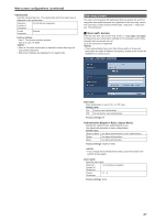
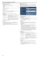
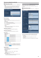
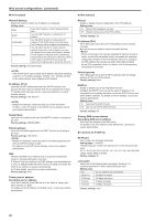
Web screen configurations (continued) Digital Extender Enable or disable the digital extender. When this is set to [On], the digital zoom will be fixed at 1.4x. When [Digital Zoom] is set to [Enable], [Digital Extender] is disabled. Setting value: Off Disable the digital extender function. On Enable the digital extender function. Tally "Enable" or "Disable" is set here for the function which turns on or turns off the tally lamp using the tally control signal. Setting value: Disable Disable the tally lamp function. Enable Enable the tally lamp function. Tally Brightness Adjust the brightness of the tally LED. Setting value: Low Low brightness Mid Medium brightness High High brightness • When this is set to [Low], the LED brightness is equivalent to that of the AW-HE120. OSD Mix Select whether to turn off/on camera menu, status, and other displays for each output image. Setting value: Off / On SDI Out HDMI Out Video Out IP When this is set to [On], the camera menu, status, and other displays for corresponding output image are displayed. Setting value: Off / On • When this is set to [Off], the camera menu can be displayed for about 1 minute after the unit is turned on. OSD Off With Tally Enable or disable the function that turns off camera menu, status, and other displays when tally signals are received via commands or contacts. When the tally signal releases, the camera menu display will return. Setting value: Off / On OSD Status Turn the status display during AWB and ABB on/off. Setting value: Off / On Model Select Set the protocol model for standard serial communication. Do not select [Reserved1] to [Reserved7]. Appears when the service switch (SW4) at the bottom of the unit is set to ON (standard serial communication). Setting value: SEVIHD1 / SBRC300 / SBRCZ330 / Reserved1 to 7 Multi-Screen setup screen The cameras whose images are to be displayed on the multi screen are set here. (→page@@, page @@) IP address Input here the IP address of the camera whose images are to be displayed on the multi screen or the host name. With one group consisting of 4 cameras, up to four groups of cameras (a total of 16 cameras) can be registered. Input as follows if the HTTP port number of the camera whose images are to be displayed has been changed. IPv4 address entry example http://192.168.0.10:8080 IPv6 address entry example http://[2001:db8:0:0:0:0:0:1]:8080 Enter the following when connecting via HTTPS. Example of input https://192.168.0.10/ Maximum number of characters 1 to 128 half-size characters Factory settings: Cam 1: selfcamera Cam 2 to Cam 16: Not registered • When connecting via HTTPS, install the security certificate for the camera to be displayed. (→page @@) • This unit is configured for cameras for which "selfcamera" is displayed for the IP address or host name. • When configuring a host name, the DNS settings of the computer that will display the multi screen must be configured. For details on the computer's DNS settings, consult your network administrator. 86
-
 1
1 -
2
-
3
-
4
-
5
-
6
-
7
-
8
-
9
-
10
-
11
-
12
-
13
-
14
-
15
-
16
-
17
-
18
-
19
-
20
-
21
-
22
-
23
-
24
-
25
-
26
-
27
-
28
-
29
-
30
-
31
-
32
-
33
-
34
-
35
-
36
-
37
-
38
-
39
-
40
-
41
-
42
-
43
-
44
-
45
-
46
-
47
-
48
-
49
-
50
-
51
-
52
-
53
-
54
-
55
-
56
-
57
-
58
-
59
-
60
-
61
-
62
-
63
-
64
-
65
-
66
-
67
-
68
-
69
-
70
-
71
-
72
-
73
-
74
-
75
-
76
-
77
-
78
-
79
-
80
-
 81
81 -
 82
82 -
 83
83 -
 84
84 -
 85
85 -
 86
86 -
 87
87 -
 88
88 -
 89
89 -
 90
90 -
 91
91 -
92
-
93
-
94
-
95
-
96
-
97
-
98
-
99
-
100
-
101
-
102
-
103
-
104
-
105
-
106
-
107
-
108
-
109
-
110
-
111
-
112
-
113
-
114
-
115
-
116
-
117
-
118
-
119
-
120
-
121
-
122
-
123
-
124
-
125
-
126
 |
 |