Panasonic AW-HE130 Operating Instructions - Page 36
Genlock adjustment, Horizontal phase adjustment
 |
View all Panasonic AW-HE130 manuals
Add to My Manuals
Save this manual to your list of manuals |
Page 36 highlights
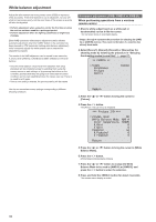
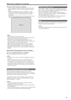
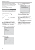
Genlock adjustment The genlock adjustment is performed to achieve phase alignment by applying external synchronization (genlock) when a multiple number of cameras will be used or when the unit will be used in combination with other devices. This unit supports BBS (Black Burst Sync) and tri-level sync external synchronization signals. Ask your dealer to perform this adjustment. (Use a dual-trace oscilloscope for the adjustment.) Horizontal phase adjustment Observe the waveforms of the external sync signal input (tri‑level sync signal) and video signal output on the dual‑trace oscilloscope, and use the wireless remote control or controller to bring the horizontal phase into alignment. External sync signal input (tri‑level sync signal) Video signal output Bring the horizontal phase into alignment. Example: When the tri‑level sync phase is adjusted When performing operations from a wireless remote control 1. Follow the operation steps in "Basic operations" (→ page 37) to display the Top Menu. 2. Press the or button to bring the cursor to [System]. Top Menu Camera Scene: Scene1 System Maintenance 4. Press the or button to bring the cursor to [Genlock], and press the button. The [Genlock] sub‑menu is displayed. Genlock Horizontal Phase 0 Horizontal Phase Step 1 Return 5. Press the or button to bring the cursor to [Horizontal Phase], and press the button. The [Horizontal Phase] value starts blinking. 6. Press the or button to change the [Horizontal Phase] value, adjust the value so that the horizontal phase is brought into alignment, and press the button. The extent of the phase adjustment can be selected using [Horizontal Phase Step]. 7. Press and hold the button for about 2 seconds. The camera menu display is exited. When performing operations from a controller These operations can be performed using the camera menus by following the operation steps in "Basic operations" "Basic operations" (→pages 37 to 46). 3. Press the button. The [System] screen appears. System Genlock Output Others Return 36
-
 1
1 -
2
-
3
-
4
-
5
-
6
-
7
-
8
-
9
-
10
-
11
-
12
-
13
-
14
-
15
-
16
-
17
-
18
-
19
-
20
-
21
-
22
-
23
-
24
-
25
-
26
-
27
-
28
-
29
-
30
-
 31
31 -
 32
32 -
 33
33 -
 34
34 -
 35
35 -
 36
36 -
 37
37 -
 38
38 -
 39
39 -
 40
40 -
 41
41 -
42
-
43
-
44
-
45
-
46
-
47
-
48
-
49
-
50
-
51
-
52
-
53
-
54
-
55
-
56
-
57
-
58
-
59
-
60
-
61
-
62
-
63
-
64
-
65
-
66
-
67
-
68
-
69
-
70
-
71
-
72
-
73
-
74
-
75
-
76
-
77
-
78
-
79
-
80
-
81
-
82
-
83
-
84
-
85
-
86
-
87
-
88
-
89
-
90
-
91
-
92
-
93
-
94
-
95
-
96
-
97
-
98
-
99
-
100
-
101
-
102
-
103
-
104
-
105
-
106
-
107
-
108
-
109
-
110
-
111
-
112
-
113
-
114
-
115
-
116
-
117
-
118
-
119
-
120
-
121
-
122
-
123
-
124
-
125
-
126
 |
 |
