Sony BRCH900 Product Manual (BRC-H900 Operating Manual)
Sony BRCH900 Manual
 |
View all Sony BRCH900 manuals
Add to My Manuals
Save this manual to your list of manuals |
Sony BRCH900 manual content summary:
- Sony BRCH900 | Product Manual (BRC-H900 Operating Manual) - Page 1
Printed on recycled paper. Sony Corporation 4-422-803-11(1) HD Color Video Camera Operating Instructions _____ GB Mode d'emploi FR Manual de instrucciones ___ ES Printed in Japan BRC-H900 © 2012 Sony Corporation - Sony BRCH900 | Product Manual (BRC-H900 Operating Manual) - Page 2
Sony dealer regarding this product. Model No. BRC-H900 Serial No. WARNING To reduce the risk of fire or electric shock, do not expose this apparatus to rain or moisture. To avoid electrical shock, do not open the cabinet. Refer servicing to qualified personnel only. (For Installers only) Instruction - Sony BRCH900 | Product Manual (BRC-H900 Operating Manual) - Page 3
ce cas l'utilisateur peut être amené à prendre des mesures appropriées. Si des interférences se produisent, contactez votre service après-vente agréé Sony. Dies ist eine Einrichtung, welche die Funk-Entstörung nach Klasse A besitzt. Diese Einrichtung kann im Wohnbereich Funkstörungen verursachen - Sony BRCH900 | Product Manual (BRC-H900 Operating Manual) - Page 4
BRC-H900 Cameras from a Long Distance 15 Operating Multiple BRC-H900 Cameras from Short and Long Distance 16 Transmitting Audio Signals Using the BRU-SF10 17 Location and Function of Parts 18 Camera 18 Remote Commander (supplied 20 RM-BR300 Remote Control Unit (not supplied 22 BRU-SF10 HD - Sony BRCH900 | Product Manual (BRC-H900 Operating Manual) - Page 5
Input Connector 67 Connecting a VTR Equipped with HD-SDI Input Connectors 68 Connecting the BRU-SF10 HD Optical Multiplex Unit 68 Connecting a Video Switcher 70 Connecting a Sync Signal Generator 70 Appendix List of Messages 72 Troubleshooting 73 Menu Configuration 75 Presetting Items 78 - Sony BRCH900 | Product Manual (BRC-H900 Operating Manual) - Page 6
noise occurs, consult your Sony dealer. Camera function setting Before setting the function of the camera such as pan/ tilt, angle of view, zooming, etc., install the camera suitably and fix the camera securely. If you change the camera's installation after setting functions, differences may arise - Sony BRCH900 | Product Manual (BRC-H900 Operating Manual) - Page 7
) The white flecks may be reduced by turning the camera off, then on again. Aliasing When fine patterns, elements (CMOS image sensors) for reading video signals, subjects that quickly move across the with the FLICKER CANCEL function. It is recommend to set the shutter speed to 1/100 sec. in the areas - Sony BRCH900 | Product Manual (BRC-H900 Operating Manual) - Page 8
image transmission and pan/tilt/zoom control • Combined use of the BRBK-SF1 HD Optical Multiplex Card, CCFC-S200 Optical Fiber Cable and BRU-SF10 Optical Multiplex Unit, and Sony unique camera connection technology and optical digital multiplex transmission technology, allows a long distance - Sony BRCH900 | Product Manual (BRC-H900 Operating Manual) - Page 9
lamp on the rear side of the camera enables good visual recognition from behind the camera. System Components In order to support multiple system configurations, a variety of optional products are available for the BRCH900 HD Color Video Camera. This section introduces these optional products as - Sony BRCH900 | Product Manual (BRC-H900 Operating Manual) - Page 10
(1) Operating Instructions (1) Optional Products RM-BR300 Remote Control Unit Ceiling bracket (B) (1) Wire rope (1) The joystick of the Remote Control Unit allows you comfortable pan/tilt and zoom operations. The Remote Control Unit also allows remote operation of up to seven cameras. Supplied - Sony BRCH900 | Product Manual (BRC-H900 Operating Manual) - Page 11
camera to allow high-bit multiplex transfer via optical fiber cable (video, audio, external video sync and control signals). BRBK-HSD2 HD/SD-SDI Output Card The HD Insert the card into the camera to allow output of an HDSDI signal conforming to SMPTE 292 serial digital interface standards, or output - Sony BRCH900 | Product Manual (BRC-H900 Operating Manual) - Page 12
Commander This system allows you: To operate the camera readily from a short distance System configuration BRC-H900 HD video monitor Remote Commander (supplied) Video signal Signal flow Operating a BRC-H900 Camera Using the RM-BR300 Remote Control Unit This system allows you: To perform pan - Sony BRCH900 | Product Manual (BRC-H900 Operating Manual) - Page 13
• To operate up to seven cameras remotely using a single Remote Control Unit • To perform pan/tilt and zoom operations using the joystick System configuration BRC-H900 HD video monitor BRC-H900 BRC-H900 Video switcher RM-BR300 Remote Control Unit Video signal Remote control (VISCA) signal Tally - Sony BRCH900 | Product Manual (BRC-H900 Operating Manual) - Page 14
pan/tilt and zoom operations using the joystick • To transmit the video and control signals of the camera to a distant place using the Optical Fiber Cable System configuration HD video monitor BRC-H900 CCFC-S200 Optical Fiber Cable BRBK-SF1 HD Optical Multiplex Card BRU-SF10 Optical Multiplex Unit - Sony BRCH900 | Product Manual (BRC-H900 Operating Manual) - Page 15
• To transmit the video and control signals of the cameras to a distant place using the Optical Fiber Cable System configuration BRC-H900 BRC-H900 CCFC-S200 Optical Fiber Cable BRU-SF10 Optical Multiplex Unit BRBK-SF1 HD Optical Multiplex Card HD video monitor BRC-H900 CCFC-S200 BRBK-SF1 - Sony BRCH900 | Product Manual (BRC-H900 Operating Manual) - Page 16
from a distance up to 2,000 m (6,562 feet) and to transmit the video and control signals of the cameras to a distant place using the Optical Fiber Cable System configuration BRC-H900 HD video monitor BRC-H900 BRC-H900 BRC-H900 CCFC-S200 BRBK-SF1 CCFC-S200 Optical Fiber Cable BRU-SF10 BRBK-SF1 - Sony BRCH900 | Product Manual (BRC-H900 Operating Manual) - Page 17
joystick • To transmit the video and control signals of the camera, and the audio signal input to the BRBK-SF1 Optical Multiplex Card, to a distant place using the Optical Fiber Cable System configuration BRC-H900 Microphone Microphone amplifier HD video monitor Speakers Audio amplifier BRBK - Sony BRCH900 | Product Manual (BRC-H900 Operating Manual) - Page 18
and ring outside the lens when energized. It may cause a malfunction of the camera. B Tally lamp Lights in red when a VISCA tally command is received or the camera is selected by the RMBR300 Remote Control Unit (not supplied) (depending on the setting mode). You can set the brightness of the tally - Sony BRCH900 | Product Manual (BRC-H900 Operating Manual) - Page 19
as a composite video signal. R S VIDEO connector Outputs the camera images as an S video signal. S SDI connector Outputs the video signal from the camera as an HD/ SD-SDI signal. Supplies down-converted SD-SDI signals that conform to the SMPTE 259M serial digital interface standards, or HD-SDI - Sony BRCH900 | Product Manual (BRC-H900 Operating Manual) - Page 20
order by pressing the POWER button while holding down the RESET button on the RMBR300 Remote Control Unit. You can assign the camera address "1" to "7" manually by setting these selectors as follows: Camera address Switch 1 Switch 2 Switch 3 0 12 3 4567 OFF ON OFF ON OFF ON OFF ON OFF OFF - Sony BRCH900 | Product Manual (BRC-H900 Operating Manual) - Page 21
b to change the set values. E L/R DIRECTION SET button Hold down this button and press the REV button to change the direction of the camera movement opposite to that the T (telephoto) side of the button to zoom in, and the W (wide angle) side to zoom out. To install batteries Two R6 (size AA) - Sony BRCH900 | Product Manual (BRC-H900 Operating Manual) - Page 22
Overview RM-BR300 Remote Control Unit (not supplied) This manual explains the operations of the RM-BR300 Remote Control Unit when it is used with BRC-H900 cameras. Front 890qaqsqd qf 1 2 3 4 5 6 7 VALUE LOCK - + R BRIGHT MODE - + B FOCUS AUTO AUTO MANUAL NEAR FAR ONE PUSH AF RESET - Sony BRCH900 | Product Manual (BRC-H900 Operating Manual) - Page 23
AUTO or SPOT LIGHT is selected with MODE of the EXPOSURE menu, hold down the SHIFT button and press this button to set the spotlight compensation function of the camera to on/off. Each time you press this button, the spotlight compensation function toggles between on and off. L PAN-TILT RESET button - Sony BRCH900 | Product Manual (BRC-H900 Operating Manual) - Page 24
BRC-Z700 BRC-Z330 BRC-H900 Note Set the selector to position 9 when all the connected cameras are BRC-H900s. For other connections, set the selector to position 0. V VISCA RS-232C connector Connect to the VISCA RS-232C IN connector of the camera or the BRU-SF10 HD Optical Multiplex Unit. W VISCA - Sony BRCH900 | Product Manual (BRC-H900 Operating Manual) - Page 25
video format settings light in green. For details on configuring these settings, see "Q VISCA FUNCTION switches" on page 26. H DATA MIX switch When the SD indicator is lit, set CAMERA connector Connect to the optical connector of the BRBK-SF1 HD Optical Multiplex Card installed in the BRC-H900 camera - Sony BRCH900 | Product Manual (BRC-H900 Operating Manual) - Page 26
external video sync Connect to the VISCA RS-422 connector of the camera or another BRC-H900 HD Optical Multiplex Unit. For the connection to the the RM-BR300 Remote Control Unit (not supplied). You can assign the camera address "1" to "7' manually by setting these selectors as follows: Camera 0 1 2 - Sony BRCH900 | Product Manual (BRC-H900 Operating Manual) - Page 27
27. Notes • SD-SDI and HD-SDI signals cannot be supplied simultaneously. • Set the panel switch before turning on the camera. • Do not push the switch forcibly with a screwdriver, etc. Images when menu display is ON When a BRBK-HSD2 is installed in the BRC-H900 card slot BRBK-HSD2 panel switch - Sony BRCH900 | Product Manual (BRC-H900 Operating Manual) - Page 28
is installed in the BRC-H900 HD Color Video Camera and menu display for the camera is turned ON, the menu display is overlapped with the image. • When a BRBK-SA1 Analog SD Output Card is installed in a BRU-SF10 HD Optical Multiplex Unit on which the front panel DATA MIX switch is set to ON and menu - Sony BRCH900 | Product Manual (BRC-H900 Operating Manual) - Page 29
on the supplied Remote Commander or the MENU button on the RM-BR300 Remote Control Unit. OPT >EXPOSURE COLOR DETAIL COLOR DETAIL KNEE GAMMA FLICKER CANCEL FOCUS PAN TILT SYSTEM VIDEO OUT SD SD-SDI 1 Cursor Selects a setting menu. Move the cursor up or down by pressing the V or - Sony BRCH900 | Product Manual (BRC-H900 Operating Manual) - Page 30
Control Unit (not supplied). For details on each menu, see pages 32 through 42. Menu Operation Using the Supplied Remote Commander 1 POWER SELECT CAMERA 2 1 FOCUS 3 MANUAL CANCEL FOCUS PAN TILT SYSTEM VIDEO OUT SD SD-SDI 2 Move the cursor to the menu item to be set by pressing the V or - Sony BRCH900 | Product Manual (BRC-H900 Operating Manual) - Page 31
Adjusting and Setting With Menus Menu Operation Using the RMBR300 Remote Control Unit 1 2, 4, 5 VALUE LOCK - + R BRIGHT MODE - + B FOCUS AUTO AUTO MANUAL NEAR FAR ONE PUSH AF RESET PRESET SHIFT L/R DIRECTION POWER PANEL LIGHT BLACK LIGHT PAN-TILT ONE PUSH RESET AWB MENU - Sony BRCH900 | Product Manual (BRC-H900 Operating Manual) - Page 32
dB when MODE is set to MANUAL. SPEED: When MODE is set to MANUAL or SHUTTER Pri, set to OFF. AGC (auto gain control) Set the automatic gain control function for a dark subject. When AGC is set to OFF, GAIN is set to 0 even if the subject becomes dark. This function is available when MODE is set - Sony BRCH900 | Product Manual (BRC-H900 Operating Manual) - Page 33
on the top of the joystick or the ONE PUSH AWB button on the RM-BR300 Remote Control Unit. MANUAL: Adjusts the white balance manually. When you select any mode of WHITE BALANCE, some of the following setting items that are required for the selected mode appear. SPEED (white balance speed): You can - Sony BRCH900 | Product Manual (BRC-H900 Operating Manual) - Page 34
The adjustable range is -7 to +7. The color intensity increases in the + direction, and decreases in the - direction. This function is not available when MATRIX is set to OFF. PHASE: Adjusts the tint of entire picture. The adjustable range is -99 to +99. This function is not available when MATRIX is - Sony BRCH900 | Product Manual (BRC-H900 Operating Manual) - Page 35
enhancer signal that is added to black side. The adjustable range is -99 to +99. This function is not available when SETTING is set to OFF. V DTL CREATION: Sets the original signal for creating the vertical image enhancer signal. The available item is NAM (either G or R, whichever is the greater - Sony BRCH900 | Product Manual (BRC-H900 Operating Manual) - Page 36
shot. When this setting is set to OFF, you can set the level point that the KNEE function is activated manually independently of the brightness same effect as CINE1. For using the picture within 100% video signal when editing, select this setting. CINE3: The contrast of the dark and bright area is - Sony BRCH900 | Product Manual (BRC-H900 Operating Manual) - Page 37
of the dark area. BLACK Adjusts the master black level. The adjustable range is - 99 to +99. The larger the setting level, the higher the black level. The lower the setting level, the lower the black level. FLICKER CANCEL Menu The FLICKER CANCEL menu is used to adjust the flicker cancel function - Sony BRCH900 | Product Manual (BRC-H900 Operating Manual) - Page 38
. Use the FAR/ NEAR buttons on the supplied Remote Commander to adjust the focus. Note Adjust the focus manually by setting MODE to MANUAL when the noise increases because the gain level is high or when you shoot: • a flat subject with low contrast such as a white wall. • a subject through - Sony BRCH900 | Product Manual (BRC-H900 Operating Manual) - Page 39
the menu using the supplied Remote Commander. To set it to OFF, use the RM-BR300 Remote Control Unit (not supplied) or the VISCA command. IMG FLIP (image flip) Set IMG FLIP to ON to rotate the camera image supplied from the RGB/COMPONENT, S VIDEO, T VIDEO, and SDI OUT connector and the connector on - Sony BRCH900 | Product Manual (BRC-H900 Operating Manual) - Page 40
is set to OFF, the display of this message is also canceled. SYNC MASTER When you connect a sync signal generator, you can select an output video signal that is synchronized with the external video sync signal input to the EXT SYNC IN connector on the camera. When connecting the BRU-SF10 HD Optical - Sony BRCH900 | Product Manual (BRC-H900 Operating Manual) - Page 41
Adjusting and Setting With Menus VIDEO OUT Menu HD-RGB/COMPONENT >FORMAT SYNC TYPE SD-VIDEO/S VIDEO IMG SIZE SETUP YPbPr SYNC 16:9[LETTER] OFF HD-RGB/COMPONENT FORMAT Select the signal output from the RGB/ COMPONENT connector on the camera. YPbPr: Outputs analog component signals. - Sony BRCH900 | Product Manual (BRC-H900 Operating Manual) - Page 42
in the BRC-H900 HD Color Video Camera, the IMG SIZE settings in the SD-SDI menu and VIDEO OUT menu are linked. • If you change the IMG SIZE setting in the SD-SDI menu, the IMG SIZE setting for outputs from the VIDEO and S VIDEO connectors on the BRC-H900 HD Color Video Camera will also change - Sony BRCH900 | Product Manual (BRC-H900 Operating Manual) - Page 43
. • If you change the IMG SIZE setting in the SD menu, the IMG SIZE setting for outputs from the VIDEO and S VIDEO connectors on the BRC-H900 HD Color Video Camera will also change. • If you change the IMG SIZE setting in the VIDEO OUT menu, the IMG SIZE setting for all outputs from the BRBK-SA1 - Sony BRCH900 | Product Manual (BRC-H900 Operating Manual) - Page 44
Turning on the Power 1 2 3 4 5 6 7 8 9 1 2 3 IR SELECT VISCA RS-422 OFF ON 75 R HD SD RGB/COMPONENT IN VISCA RS-232 OUT EXT SYNC IN VIDEO S VIDEO SDI OUT DC IN 12V to the AC adaptor (supplied) POWER lights 1 Connect the camera to an AC outlet using the supplied AC power adaptor and power - Sony BRCH900 | Product Manual (BRC-H900 Operating Manual) - Page 45
Commander that corresponds to the number set in step 1. STANDBY flashes POWER CAMERA SELECT 1 2 3 AUTO FOCUS MANUAL FAR NEAR DATA SCREEN BACK LIGHT CAMERA SELECT You can then operate the camera(s) specified by number. Every time you operate the camera(s) using the Remote Commander, the - Sony BRCH900 | Product Manual (BRC-H900 Operating Manual) - Page 46
W W RM-EV100 DIREL/CRTION SET Focusing on a Subject To focus the camera on a subject automatically Press the AUTO button. The camera focuses on the subject at the center of the screen automatically. To focus the camera on a subject manually After pressing the MANUAL button, press either the FAR - Sony BRCH900 | Product Manual (BRC-H900 Operating Manual) - Page 47
Commander supports preset of six positions only (POSITION 1 to 6). Use the RM-BR300 Remote Control Unit (not supplied) to store the settings in POSITION 7 to 16. For details of the camera settings to be preset, see "Presetting Items" on page 78. POWER CAMERA SELECT 2 1 FOCUS FAR 3 MANUAL - Sony BRCH900 | Product Manual (BRC-H900 Operating Manual) - Page 48
follows. Then you can switch the camera to be controlled simply by pressing the corresponding CAMERA button. To assign camera addresses automatically 1 Make sure that the camera address selector on the bottom of each camera is set to "0." For setting the camera address selector, see page 19. 2 Turn - Sony BRCH900 | Product Manual (BRC-H900 Operating Manual) - Page 49
you can switch the camera you want to control with the Remote Control Unit by pressing the CAMERA button. To assign camera addresses manually Set one of the camera addresses, 1 to 7, using the camera address selectors on the bottom of each camera. For setting the camera address selectors, see page - Sony BRCH900 | Product Manual (BRC-H900 Operating Manual) - Page 50
. While holding down L/R DIRECTION 2 10 REV Press. Note The setting above only changes the signal emitted from the RM-BR300 Remote Control Unit, and does not change the setting of the camera itself. If the STANDBY lamp of the camera flashes When the camera is moved or turned by hand or by external - Sony BRCH900 | Product Manual (BRC-H900 Operating Manual) - Page 51
in the center of the screen automatically. AUTO AUTO MANUAL To focus the camera on a subject manually Press the AUTO/MANUAL button so that the AUTO indicator turns off. Then turn the FOCUS control clockwise or counterclockwise to have the camera focus on the subject. Focusing on a near subject - Sony BRCH900 | Product Manual (BRC-H900 Operating Manual) - Page 52
on the Remote Control Unit, the functions of the R control and B control change according to the WHITE BALANCE setting in the COLOR menu of the camera. WHITE BALANCE setting MANUAL AUTO, ONE PUSH R control B control Red gain control OFFSET control Blue gain control OFFSET control Adjusting the - Sony BRCH900 | Product Manual (BRC-H900 Operating Manual) - Page 53
zooming, focusing, and backlighting, can be stored in the memory of the camera using the RM-BR300 Remote Control Unit. For details of the camera settings to be preset, see "Presetting Items" on page 78. Storing Camera Settings To select positions 9 to 16 While holding down the SHIFT button, press - Sony BRCH900 | Product Manual (BRC-H900 Operating Manual) - Page 54
sec. 11 degrees/sec. 23.3 degrees/sec. 43 degrees/sec. 60 degrees/sec. (default) Now the camera will move to the position preset to the pressed POSITION button with the selected speed. To set the camera's movement speed to a preset position between 9 and 16 Hold down the SHIFT button and press the - Sony BRCH900 | Product Manual (BRC-H900 Operating Manual) - Page 55
Installation and Connections Installation Attaching an Interface Card Attach an Interface Card (not supplied) to the card slot on the rear of the camera. 1 Loosen the two screws to remove the card slot cover. 2 Insert an optional Interface Card into the card slot. Align both ends of the card - Sony BRCH900 | Product Manual (BRC-H900 Operating Manual) - Page 56
. • Do not grasp the camera head when carrying the camera. • Do not turn the camera head by hand. Doing so may result in the camera malfunctioning. To attach the camera to a tripod Attach a tripod to the tripod screw hole on the bottom of the camera. The tripod must be set up on a flat surface and - Sony BRCH900 | Product Manual (BRC-H900 Operating Manual) - Page 57
The ceiling bracket cannot be attached to a junction box when installing the camera on a ceiling. Installation on a ceiling (example) 1 Set IMG FLIP to ON in the SYSTEM menu. 2 Remove the four screws on the bottom of the camera to remove the four feet. 3 Attach the ceiling bracket (A) to the bottom - Sony BRCH900 | Product Manual (BRC-H900 Operating Manual) - Page 58
the ceiling bracket (A) aligned with the hole on the ceiling bracket (B), and temporarily attach them by turning the ceiling bracket (A) with the camera clockwise. Ceiling M5 (3/16 inch) hexagon socket head cap screw Ceiling bracket (B) 6 Attach the wire rope to the ceiling bracket (A). Pass the - Sony BRCH900 | Product Manual (BRC-H900 Operating Manual) - Page 59
AC power cord and DC-cord secure connection attachment, see "Connections" on page 63. 10 The SONY and/or HD nameplates can be turned upside down, if necessary. To remove the camera 1 Remove the three screws used to attach the camera in step 8 of "Installation on a ceiling (example)." 2 Turn the - Sony BRCH900 | Product Manual (BRC-H900 Operating Manual) - Page 60
(3M4 × 8). Wire rope (supplied) 3M4 × 8 (supplied) Fixing hole for wire rope Ceiling bracket (A) 4 Attach the ceiling bracket (B) to a shelf, etc., on which the camera is to be installed. Use four screws (not supplied) appropriate for the materials of the shelf, etc. Align the f hole on the ceiling - Sony BRCH900 | Product Manual (BRC-H900 Operating Manual) - Page 61
the ceiling bracket (A) aligned with the hole on the ceiling bracket (B), then temporarily attach them by turning the ceiling bracket (A) with the camera counterclockwise. Wire rope (supplied) M5 (3/16 inch) hexagon socket head cap screw Ceiling bracket (B) Ceiling bracket (A) a hole Align. hole - Sony BRCH900 | Product Manual (BRC-H900 Operating Manual) - Page 62
7 Secure the ceiling brackets (A) and (B) using the supplied three screws (3M3 × 8). 8 Connect the cables to the connectors on the rear of the camera. Installation and Connections 3M3 × 8 (supplied) 62 GB Installation Notes • Take the proper steps and make sure that the weight of the connected - Sony BRCH900 | Product Manual (BRC-H900 Operating Manual) - Page 63
Outlet Use the supplied AC power adaptor and AC power cord to connect the camera to an AC outlet. 1 2 3 4 5 6 7 8 9 1 2 3 IR SELECT VISCA RS-422 OFF ON 75 R HD SD RGB/COMPONENT IN VISCA RS-232 OUT EXT SYNC IN VIDEO S VIDEO SDI OUT DC IN 12V DC IN 12V AC power adaptor MPA-AC1 - Sony BRCH900 | Product Manual (BRC-H900 Operating Manual) - Page 64
9 1 2 3 IR SELECT VISCA RS-422 OFF ON 75 R HD SD RGB/COMPONENT IN VISCA RS-232 OUT EXT SYNC IN VIDEO S VIDEO SDI OUT DC IN 12V to the AC adaptor VISCA RS-232C IN on the bottom of the camera (page 19) and the DIP switch on the bottom of the Remote Control Unit (page 24) are set to RS-422. • - Sony BRCH900 | Product Manual (BRC-H900 Operating Manual) - Page 65
(supplied with the RM-BR300) VISCA RS-232C IN 1 2 3 4 5 6 7 8 9 1 2 3 IR SELECT VISCA RS-422 OFF ON 75 R HD SD RGB/COMPONENT IN VISCA RS-232 OUT EXT SYNC IN VIDEO S VIDEO SDI OUT DC IN 12V First BRC-H900 to the AC adaptor (supplied) VISCA RS-232C OUT RS-232C cable VISCA RS-232C IN - Sony BRCH900 | Product Manual (BRC-H900 Operating Manual) - Page 66
-BR300 Remote Control Unit VISCA RS-422 VISCA RS-422 cable to the AC adaptor (supplied with the RM-BR300) VISCA RS-422 1 2 3 4 5 6 7 8 9 1 2 3 IR SELECT VISCA RS-422 OFF ON 75 R HD SD RGB/COMPONENT IN VISCA RS-232 OUT EXT SYNC IN VIDEO S VIDEO SDI OUT DC IN 12V First BRC-H900 to the AC - Sony BRCH900 | Product Manual (BRC-H900 Operating Manual) - Page 67
Video or S Video Input Connector Connecting a Video Monitor, VTR, etc., Equipped with SDI Input Connector Set the HD/SD select switch on the camera to SD, and turn on the camera. You can output the signal from the camera by converting it into an SDI signal that conforms to SMPTE 259M serial digital - Sony BRCH900 | Product Manual (BRC-H900 Operating Manual) - Page 68
Fiber Cable. This allows you to control the camera from up to 2,000 m (6,562 feet) away. HD camera BRC-H900 Installation and Connections 1 2 3 4 5 6 7 8 9 1 2 3 IR SELECT VISCA RS-422 OFF ON 75 R HD SD RGB/COMPONENT IN VISCA RS-232 OUT EXT SYNC IN VIDEO S VIDEO SDI OUT DC IN 12V to the - Sony BRCH900 | Product Manual (BRC-H900 Operating Manual) - Page 69
the Optical Multiplex Unit (page 26) and the DIP switch on the bottom of the Remote Control Unit (page 24) are set to RS-232C or RS-422 correctly. Notes on use of the CCFC-S200 HD Optical Fiber Cable • In order to prevent cable transmission loss, keep away bend in the cable - Sony BRCH900 | Product Manual (BRC-H900 Operating Manual) - Page 70
signals to be output. Third to Seventh BRC-900 Connecting a Sync Signal Generator To connect a single camera Installation and Connections 123456789 123 IR SELECT VISCA RS-422 OFF ON 75 R HD SD RGB/COMPONENT IN VISCA RS-232 OUT EXT SYNC IN VIDEO S VIDEO SDI OUT DC IN 12V VISCA RS-232C - Sony BRCH900 | Product Manual (BRC-H900 Operating Manual) - Page 71
connect up to seven cameras. Third to Seventh (last) BRC-H900 Commercially available T-type signal separator Commercially available T-type signal separator 1 2 3 4 5 6 7 8 9 1 2 3 IR SELECT VISCA RS-422 OFF ON 75 R HD SD RGB/COMPONENT IN VISCA RS-232 OUT EXT SYNC IN VIDEO S VIDEO SDI OUT DC - Sony BRCH900 | Product Manual (BRC-H900 Operating Manual) - Page 72
back tally lamp Turn off the power of the camera, then flashes. consult your Sony dealer. Messages for the BRC-H900 camera Message Meaning/remedies Please restart system! You are prompted to restart the power of the camera after you changed the setting of "IMG FLIP" in the SYSTEM menu. Use - Sony BRCH900 | Product Manual (BRC-H900 Operating Manual) - Page 73
Before bringing in your camera for service, check the following guide to troubleshoot the problem. If the problem cannot be corrected, consult your Sony dealer. Symptom Cause Remedy The power of the camera is not turned The supplied AC power adaptor is not on. connected to the DC - Sony BRCH900 | Product Manual (BRC-H900 Operating Manual) - Page 74
camera. the camera. computer and camera is made correctly. Check that the VISCA control setting (RS232C or RS-422) and the baud rate setting the dealer for details. from that from the camera connected to a expected picture quality. video monitor. The camera cannot be operated at all. - Pull - Sony BRCH900 | Product Manual (BRC-H900 Operating Manual) - Page 75
camera are configured as described below. For more information, refer to the pages indicated in parentheses. The initial settings 18, 19, 20, 21, 22, 23, 24dB (Adjustable only when MODE in the EXPOSURE menu is set to MANUAL.) For the 1080/59.94i or 720/59.94p signal format: 1/60, 1/100, 1/120, 1/125, - Sony BRCH900 | Product Manual (BRC-H900 Operating Manual) - Page 76
+99 ON, OFF 50Hz, 60Hz FOCUS (page 38) MODE AUTO, MANUAL PAN TILT (page 38) SYSTEM (page 39) PAN LEFT RIGHT TILT VIDEO OUT (page 41) FORMAT RGB, YPbPr ADD SYNC RGB, OFF SYNC TYPE VD, SYNC IMG SIZE 16:9 [LETTER], 4:3 [CROP], 4:3 [SQUEEZE] SET UP1) ON, OFF 1)Does not appear when an HD - Sony BRCH900 | Product Manual (BRC-H900 Operating Manual) - Page 77
) D-SUB OUTPUT 1 D-SUB OUTPUT 2 IMG-SIZE SETUP1) YCbCr RGB ADD SYNC VBS Y/C 16:9 [LETTER] 4:3 [CROP] 4:3 [SQUEEZE] OFF ON RGB OFF 1)Does not appear when an HD output signal is 1080/50i or 720/50p format. Appendix 77 Menu Configuration GB - Sony BRCH900 | Product Manual (BRC-H900 Operating Manual) - Page 78
can be stored in the memory of the camera. General presetting items Presetting item Presetting position number 1 2 - 16 Pan/tilt position z a ZOOM position z a FOCUS position (only when z a MODE in the EXPOSURE menu set to MANUAL) Presetting menu items Presetting item EXPOSURE MODE - Sony BRCH900 | Product Manual (BRC-H900 Operating Manual) - Page 79
COLOR BAR TALLY MODE FORMAT (HD OUTPUT) ADD SYNC SYNC TYPE IMG SIZE (SD in the BRC-H900 and in use, the IMG SIZE setting is linked with the VIDEO OUT setting. When camera starts with these settings. a : Setting items are stored in memory. Recall the settings by selecting the preset number. s : Setting - Sony BRCH900 | Product Manual (BRC-H900 Operating Manual) - Page 80
Effective picture elements: Approx. 2,070,000 pixels Lens 14× (optical) Filter diameter: 77 mm (Wide/tele conversion lens cannot be attached.) f = 5.8 to 81.2 mm, F1.9 to F16 f = 31.4 to 439 mm (equivalent to the focal length of a 35-mm camera) Minimum object distance 800 mm (31 1/2 inches - Sony BRCH900 | Product Manual (BRC-H900 Operating Manual) - Page 81
RS-422 connector plug (1) DC-cord secure connection attachment (1) Operating Instructions (1) Design and specifications are subject to change without notice. Note Always verify that the unit is operating properly before use. SONY WILL NOT BE LIABLE FOR DAMAGES OF ANY KIND INCLUDING, BUT - Sony BRCH900 | Product Manual (BRC-H900 Operating Manual) - Page 82
Dimensions BRC-H900 Video Camera Top Front Side Bottom Tripod screw hole 2 3 . 1 (15/16) 20 (13/16) ( 25)0 Appendix Ceiling Bracket (B) Top 9 0 ˚ 2 30 0 (13 ˚ / 16 ) ø 1 8 6 3 (7 /8) Side 20˚ 50(2) ø ( 161 63 / 8) ( - Sony BRCH900 | Product Manual (BRC-H900 Operating Manual) - Page 83
Control Unit Top 137.2 (5 1/2) VALUE LOCK - + R BRIGHT MODE - + B FOCUS AUTO AUTO MANUAL NEAR ONE PUSH FAR AF RESET PRESET SHIFT L/R DIRECTION POWER PANEL LIGHT BLACK PAN-TILT ONE PUSH LIGHT RESET AWB MENU POSITION 12345678 9 10 11 12 13 14 15 16 STD REV CAMERA - Sony BRCH900 | Product Manual (BRC-H900 Operating Manual) - Page 84
BRU-SF10 HD Optical Multiplex Unit Top Side Front Unit: mm (inches) Appendix 84 GB Specifications - Sony BRCH900 | Product Manual (BRC-H900 Operating Manual) - Page 85
Pin Assignments BRC-H900 Video Camera VISCA RS-422 connector (connector plug 9-pin) VISCA RS-422 123456789 Pin No. 1 2 3 4 5 6 7 8 9 GND GND 12 NC NC NC 13 HD-OUT HD-OUT HD-OUT 14 Tri-level Bi-level VD- Tri-level SYNC-OUT OUT SYNC- OUT 15 NC NC NC At RGB setting (at VD) R-OUT G-OUT B- - Sony BRCH900 | Product Manual (BRC-H900 Operating Manual) - Page 86
RM-BR300 Remote Control Unit (optional) VISCA RS-232C output connector (mini DIN 8pin, female) 2 3 4 5 6 7 8 9 Function CAMERA1 CAMERA2 CAMERA3 CAMERA4 CAMERA5 CAMERA6 CAMERA7 GND GND BRU-SF10 HD Optical Multiplex Unit (optional) VISCA RS-232C IN connector (mini DIN 8-pin, female) IN Pin No. 1 - Sony BRCH900 | Product Manual (BRC-H900 Operating Manual) - Page 87
NC 10 GND GND GND 11 GND GND GND 12 NC NC NC 13 HD-OUT HD-OUT HD-OUT 14 Tri-level Bi-level VD- Tri-level SYNC-OUT OUT SYNC- OUT 15 NC NC NC At RGB setting (at VD) R-OUT G-OUT B-OUT GND GND GND GND GND NC GND GND NC - Sony BRCH900 | Product Manual (BRC-H900 Operating Manual) - Page 88
Control Unit VISCA RS-422 connector 1 NC 2 NC 3 NC 4 NC 5 GND 6 RXD IN - 7 RXD IN + 8 TXD IN - 9 TXD IN + NC = No Connection Third to Seventh BRC-H900 RXD IN - 7 RXD IN + 8 TXD IN - 9 TXD IN + First BRC-H900 camera or BRUSF10 HD Optical Multiplex Unit VISCA RS-422 connector 1 RXD OUT - 2 RXD OUT + 3 - Sony BRCH900 | Product Manual (BRC-H900 Operating Manual) - Page 89
Using the VISCA RS-422 Connector Plug 1 Insert a wire (AWG Nos. 28 to 18) into the desired wire opening on the VISCA RS-422 connector plug, and tighten the screw for that wire using a flathead screwdriver. To remove the connector plug Grasp both ends of the VISCA RS-422 connector plug and pull it - Sony BRCH900 | Product Manual (BRC-H900 Operating Manual) - Page 90
Instructions pour l'installation de l'équipement au plafond : Après l'installation, assurez-vous que le montage est suffisamment solide pour supporter produisent, contactez votre service après-vente agréé Sony. Pour les clients en Europe Le fabricant de ce produit est Sony Corporation, 1-7-1 Konan, - Sony BRCH900 | Product Manual (BRC-H900 Operating Manual) - Page 91
BRC-H900 au moyen du pupitre de télécommande RM-BR300 12 Commande d'une caméra BRC-H900 depuis une longue distance 13 Menu FOCUS 38 Menu PAN TILT 39 Menu SYSTEM 40 Menu VIDEO RM-BR300 (non fourni 21 Module multiplex optique HD Commande de panoramique/inclinaison et de zoom 46 Panoramique - Sony BRCH900 | Product Manual (BRC-H900 Operating Manual) - Page 92
magnétoscope, etc. doté d'un connecteur d'entrée SDI 71 Raccordement d'un magnétoscope doté de connecteurs d'entrée HD-SDI 72 Raccordement du module multiplex optique HD BRU-SF10 72 Raccordement d'un sélecteur vidéo 74 Raccordement d'un générateur de signal de synchronisation 74 Annexe Liste - Sony BRCH900 | Product Manual (BRC-H900 Operating Manual) - Page 93
optimal, il est recommandé d'effectuer la maintenance de manière périodique. En cas de bruits anormaux, informez-vous auprès de votre revendeur Sony. Configuration des fonctions de la caméra Avant de configurer les fonctions de la caméra, telles que le mécanisme de panoramique/inclinaison, l'angle - Sony BRCH900 | Product Manual (BRC-H900 Operating Manual) - Page 94
Préparation Phénomènes spécifiques aux capteurs d'images CMOS Les phénomènes suivants qui peuvent apparaître dans des images sont spécifiques aux capteurs d'images CMOS (Complementary Metal Oxide Semiconductor). Ils ne sont pas un signe de mauvais fonctionnement. Mouchetures blanches Bien que les - Sony BRCH900 | Product Manual (BRC-H900 Operating Manual) - Page 95
situé sur la caméra pour reproduire un signal HD-SDI conforme à la norme d'interface numérique technologie de connexion de caméra exclusive Sony et à la technologie de transmission multiplex transmission sur de longues distances. • Les supports de montage au plafond fournis permettent d'installer - Sony BRCH900 | Product Manual (BRC-H900 Operating Manual) - Page 96
ème Divers produits sont disponibles en option pour la caméra vidéo couleur HD BRC-H900 afin de lui permettre de s'intégrer à de multiples configurations de systè les suivants. Caméra (1) Adaptateur secteur MPA-AC1 (Sony) (1) Cordon d'alimentation (1) Modèle pour les États-Unis et le Canada 8 - Sony BRCH900 | Product Manual (BRC-H900 Operating Manual) - Page 97
vis inoxydable 3M4 × 8 (1) Télécommande (1) Fiche de connecteur RS-422 (1) Exige deux piles R6 (format AA) (non fournies). Support de montage au plafond (A) (1) Support de montage au plafond (B) (1) Fixation de raccordement sécurisé du cordon CC (1) Mode d'emploi (1) Produits en option Pupitre - Sony BRCH900 | Product Manual (BRC-H900 Operating Manual) - Page 98
(3 m) (1), fiche de connecteur RS-422 (1) Câble à fibres optiques CCFC-S200 Insérez cette carte dans la caméra pour permettre la sortie d'un signal HD-SDI conforme à la norme d'interface numérique série SMPTE 292 ou la sortie d'un signal SD-SDI conforme à la norme d'interface numérique série SMPTE - Sony BRCH900 | Product Manual (BRC-H900 Operating Manual) - Page 99
Description générale Configuration du système La camera vidéo couleur HD BRC-H900 peut s'adapter à diverses configurations de de commande du pupitre de télécommande Configuration du système Moniteur vidéo HD BRC-H900 Pupitre de télécommande RM-BR300 Signal vidéo Signal de télécommande (VISCA) - Sony BRCH900 | Product Manual (BRC-H900 Operating Manual) - Page 100
• Effectuer des commandes de panoramique/inclinaison et de zoom à l'aide de la manette de commande Configuration du système BRC-H900 Moniteur vidéo HD BRC-H900 BRC-H900 Sélecteur vidéo Pupitre de télécommande RM-BR300 Signal vidéo Signal de télécommande (VISCA) Signalisation/signal de contact - Sony BRCH900 | Product Manual (BRC-H900 Operating Manual) - Page 101
au moyen du câble à fibres optiques CCFC-S200 et mettez le module BRU-SF10 sous tension. • Lorsque la carte multiplex optique HD BRBK-SF1 est insérée dans la caméra BRC-H900, le connecteur EXT SYNC IN, les connecteurs VISCA RS-232C IN/OUT et le connecteur VISCA RS-422 situés à l'arrière - Sony BRCH900 | Product Manual (BRC-H900 Operating Manual) - Page 102
du câble à fibres optiques Configuration du système BRC-H900 BRC-H900 BRC-H900 Câble à fibres optiques Module multiplex optique BRU-SF10 CCFC-S200 Carte multiplex optique HD BRBK-SF1 CCFC-S200 BRU-SF10 BRBK-SF1 Moniteur vidéo HD Sélecteur vidéo CCFC-S200 BRBK-SF1 Signal vidéo Signal - Sony BRCH900 | Product Manual (BRC-H900 Operating Manual) - Page 103
m et transmettre les signaux vidéo et de commande des caméras vers un endroit distant au moyen du câble à fibres optiques Configuration du système BRC-H900 Moniteur vidéo HD BRC-H900 BRC-H900 BRC-H900 CCFC-S200 BRBK-SF1 Câble à fibres optiques CCFC-S200 BRU-SF10 Carte multiplex optique - Sony BRCH900 | Product Manual (BRC-H900 Operating Manual) - Page 104
BRBK-SF1 vers un endroit distant au moyen du câble à fibres optiques Configuration du système BRC-H900 Microphone Moniteur vidéo HD Haut-parleurs Amplificateur de microphone Amplificateur audio Carte multiplex optique HD BRBK-SF1 Câble à fibres optiques CCFC-S200 Module multiplex optique - Sony BRCH900 | Product Manual (BRC-H900 Operating Manual) - Page 105
tat (allumé/éteint) du témoin de signalisation arrière. E Plaques signalétiques SONY et HD Tirez dessus pour les retirer et les coller dans l'autre sens si nécessaire. SELECT VISCA RS-422 OFF ON 75 R HD SD RGB/COMPONENT IN VISCA RS-232 OUT EXT SYNC IN VIDEO S VIDEO SDI OUT DC IN 12V qf qg qhqj - Sony BRCH900 | Product Manual (BRC-H900 Operating Manual) - Page 106
R Connecteur S VIDEO Reproduit les images de la caméra en signaux S-Vidéo. S Connecteur SDI Reproduit les signaux vidéo provenant de la caméra en signaux HD/SD-SDI. É haute au plafond, sur une étagère ou autre, fixez le support de montage au plafond fourni dans ces orifices au moyen des quatre vis - Sony BRCH900 | Product Manual (BRC-H900 Operating Manual) - Page 107
SELECT 1 2 3 AUTO FOCUS MANUAL FAR NEAR DATA SCREEN BACK LIGHT STD REV 123 456 PRESET RESET POSITION PAN-TILT HOME PAN-TILT RESET SLOW ZOOM FAST TT W L/R DIRECTION SET W RM-EV100 6 7 8 9 q; A Touches CAMERA SELECT Appuyez sur la touche correspondant à la caméra que vous désirez - Sony BRCH900 | Product Manual (BRC-H900 Operating Manual) - Page 108
Pour effectuer la mise au point manuellement, appuyez sur la touche MANUAL et utilisez les touches FAR et NEAR. C Touche DATA SCREEN et B ou b pour changer les valeurs spécifiées. E Touche L/R DIRECTION SET Tout en maintenant cette touche enfoncée, appuyez sur la touche REV pour inverser le sens - Sony BRCH900 | Product Manual (BRC-H900 Operating Manual) - Page 109
) Ce manuel explique l'utilisation du pupitre de télécommande RM-BR300 avec les caméras BRC-H900. Face avant 890qaqsqd qf 1 2 3 4 5 6 7 VALUE LOCK - + R BRIGHT MODE - + B FOCUS AUTO AUTO MANUAL NEAR FAR ONE PUSH AF RESET PRESET SHIFT L/R DIRECTION POWER PANEL LIGHT BLACK PAN-TILT - Sony BRCH900 | Product Manual (BRC-H900 Operating Manual) - Page 110
ra correspondant à la touche POSITION enfoncée. J Touche PANEL LIGHT Appuyez sur cette touche pour éclairer toutes les touches POSITION et les touches CAMERA. Appuyez à nouveau sur la touche pour éteindre l'éclairage. K Touche BACK LIGHT Si vous avez sélectionné FULL AUTO ou BACK LIGHT avec l'option - Sony BRCH900 | Product Manual (BRC-H900 Operating Manual) - Page 111
sur cette touche pour éclairer la ou les touches CAMERA correspondant à l'état de la ou des caméras BRC-H900. Pour les autres raccordements, réglez le sélecteur sur la position 0. V Connecteur VISCA RS-232C Raccordez-le au connecteur VISCA RS-232C IN de la caméra ou du module multiplex optique HD - Sony BRCH900 | Product Manual (BRC-H900 Operating Manual) - Page 112
pour mettre le pupitre de télécommande sous/hors tension. Module multiplex optique HD BRU-SF10 (non fourni) Face avant 1 2 345 ON/STANDBY LINK 38400bps 7 HD OPTICAL MULTIPLEX UNIT 8 A Interrupteur d'alimentation Met cet appareil sous/hors tension. Vous devez mettre la caméra BRC-H900 sous - Sony BRCH900 | Product Manual (BRC-H900 Operating Manual) - Page 113
RS232C 123456789 VISCA RS422 AUDIO OUT L FUNCTION R 1 10 DC 12 V ql qk qj I Connecteur CAMERA Raccordez-le au connecteur optique de la carte multiplex optique HD BRBK-SF1 installée dans la caméra BRC-H900, au moyen du câble à fibres optiques CCFC-S200. Un cache antipoussière a été monté en - Sony BRCH900 | Product Manual (BRC-H900 Operating Manual) - Page 114
IN 2 BRU A Prises AUDIO IN L/R (type phono) Faites entrer le signal audio (stéréo) émis par les prises AUDIO OUT sur le module multiplex optique HD BRU-SF10, via le câble à fibres optiques. Remarque L'entrée audio de cette carte accepte uniquement les signaux de ligne audio. Lors de la réception - Sony BRCH900 | Product Manual (BRC-H900 Operating Manual) - Page 115
BRC-H900 Commutateur de panneau BRBK-HSD2 Connecteur MONITOR Connecteurs SDI 1, 2 Position gauche HD/ DATA MIX : ON a (sortie HD-SDI) Position centrale HD/ DATA MIX : OFF a × (sortie HD (non fournie) 12 BRBK-SA1 VIDEO S-VIDEO 3 RGB/SYNC A Connecteur T VIDEO (type BNC) Émet des - Sony BRCH900 | Product Manual (BRC-H900 Operating Manual) - Page 116
H900 et que l'écran de menu de la caméra est réglé sur ON, l'image recouvre ce dernier. • Lorsqu'une carte de sortie SD analogique BRBK-SA1 est installée dans le module multiplex optique HD BRU-SF10 dont le commutateur DATA MIX du panneau frontal est réglé sur ON et dont l'écran de - Sony BRCH900 | Product Manual (BRC-H900 Operating Manual) - Page 117
>EXPOSURE COLOR DETAIL COLOR DETAIL KNEE GAMMA FLICKER CANCEL FOCUS PAN TILT SYSTEM VIDEO OUT SD SD-SDI 1 Curseur Sélectionne un menu de réglage. Déplacez HPHASE HPHASE FINE STEADY SHOT COLOR BAR TALLY MODE VERSION ON OFF OFF OFF ON HD 03 0 OFF OFF LOW 1.00 1 Menu de réglage Le nom du - Sony BRCH900 | Product Manual (BRC-H900 Operating Manual) - Page 118
la télécommande fournie 1 POWER CAMERA SELECT 2 1 FOCUS 3 MANUAL NEAR BACK LIGHT FAR AUTO SET 3 W RM-EV100 1 Appuyez sur la touche DATA SCREEN. Le menu principal apparaît. OPT >EXPOSURE COLOR DETAIL COLOR DETAIL KNEE GAMMA FLICKER CANCEL FOCUS PAN TILT SYSTEM VIDEO - Sony BRCH900 | Product Manual (BRC-H900 Operating Manual) - Page 119
COLOR BAR TALLY MODE VERSION ON OFF OFF OFF ON HD 03 0 OFF OFF LOW 1.00 4 Déplacez BRIGHT MODE - + B FOCUS AUTO AUTO MANUAL NEAR FAR ONE PUSH AF RESET PRESET 14 15 16 STD REV CAMERA 1234567 3 1 Appuyez sur FLICKER CANCEL FOCUS PAN TILT SYSTEM VIDEO OUT SD SD-SDI 2 Dé - Sony BRCH900 | Product Manual (BRC-H900 Operating Manual) - Page 120
HPHASE FINE STEADY SHOT COLOR BAR TALLY MODE VERSION ON OFF OFF OFF ON HD 03 0 OFF OFF LOW 1.00 Pour revenir au menu principal Appuyez sur la de la sensibilité, de la vitesse de l'obturateur électronique et de l'iris. MANUAL : La sensibilité (GAIN), la vitesse de l'obturateur électronique (SPEED) - Sony BRCH900 | Product Manual (BRC-H900 Operating Manual) - Page 121
1/1 000, 1/2 000, 1/4 000, 1/8 000 IRIS : Si MODE est réglé sur MANUAL ou IRIS Pri, sélectionnez l'iris parmi les valeurs suivantes : F1.9/F2.2/F2.4/F2.6/F2.8/F3 SHUTTER sont réglés sur OFF. AGC (Auto Gain Control) Réglez la fonction AGC (Auto Gain Control) pour un sujet sombre. Si AGC est réglé sur - Sony BRCH900 | Product Manual (BRC-H900 Operating Manual) - Page 122
des blancs parmi les suivants : AUTO, INDOOR, OUTDOOR, ONE PUSH, MANUAL AUTO : Règle automatiquement la balance des blancs. INDOOR : Les valeurs tonalité rouge dans le sens +. R. GAIN, B. GAIN : Si vous sélectionnez MANUAL, R. GAIN (gain de rouge) et B. GAIN (gain de bleu) apparaissent. Vous - Sony BRCH900 | Product Manual (BRC-H900 Operating Manual) - Page 123
s'étend de -99 à +99. Plus le niveau du réglage est élevé, plus le signal d'optimisation d'image est élevé. Cette fonction n'est pas disponible si SETTING est réglé sur OFF. FREQUENCY : Règle la fréquence centrale de l'optimisation d'image. La plage de réglage s'étend de -99 à +99. Plus le niveau - Sony BRCH900 | Product Manual (BRC-H900 Operating Manual) - Page 124
d'amélioration de l'image qui est ajouté à la teinte spécifique. La plage de réglage s'étend de -99 à +99. Cette fonction n'est pas disponible si SETTING est réglé sur OFF. AREA INDICATION : Lorsque ce réglage a la valeur ON, la zone de la couleur réglée sur le réglage d'amélioration de l'image - Sony BRCH900 | Product Manual (BRC-H900 Operating Manual) - Page 125
à STD. Lorsque CINE1, CINE2, CINE3 ou CINE4 est sélectionné, KNEE SETTING est automatiquement réglé sur OFF. Si le réglage CINE1, CINE2, CINE3 ou CINE4 est remplacé par STD1, STD2, STD3 ou STD4, KNEE SETTING est automatiquement réglé sur ON. LEVEL : Règle le niveau de la courbe - Sony BRCH900 | Product Manual (BRC-H900 Operating Manual) - Page 126
les touches FAR/NEAR de la télécommande fournie pour régler la mise au point. Remarque Effectuez manuellement la mise au point en réglant MODE sur MANUAL si le bruit augmente en raison d'un niveau de gain élevé ou lorsque vous filmez : • un sujet plan à faible contraste comme un mur blanc. • un - Sony BRCH900 | Product Manual (BRC-H900 Operating Manual) - Page 127
Réglage et configuration au moyen des menus Menu PAN TILT Le menu PAN TILT sert à sélectionner le mode de panoramique/inclinaison/zoom. >LIMIT PAN LEFT RIGHT TILT DOWN UP RAMP CURVE OFF END END OFF END END MODE2 Plage de réglage de TILT DOWN/TILT UP UP END (90°) 89° ±0° -29° PAN-TILT - Sony BRCH900 | Product Manual (BRC-H900 Operating Manual) - Page 128
externe entré au connecteur EXT SYNC IN du module multiplex optique HD BRU-SF10. HD : Sélectionne le signal de sortie du connecteur RGB/COMPONENT. SD : Sélectionne le signal de sortie du connecteur VIDEO ou S VIDEO. H PHASE Lorsque vous raccordez un générateur de signal de synchronisation, ajustez - Sony BRCH900 | Product Manual (BRC-H900 Operating Manual) - Page 129
automatiquement à 9. Remarque HPHASE et HPHASE FINE ne s'affichent pas si un module multiplex optique HD BRU-SF10 est utilisé. STEADY SHOT Vous pouvez sélectionner les effets de compensation du flou de . VERSION Informations relatives à la version du micrologiciel de la BRC-H900. 41 Menu SYSTEM FR - Sony BRCH900 | Product Manual (BRC-H900 Operating Manual) - Page 130
Réglage et configuration au moyen des menus Menu VIDEO OUT HD-RGB/COMPONENT >FORMAT SYNC TYPE SD-VIDEO/S VIDEO IMG SIZE SETUP YPbPr SYNC 16:9[LETTER] OFF HD-RGB/COMPONENT FORMAT Sélectionnez la sortie de signal du connecteur COMPONENT sur la caméra. RGB/ YPbPr : Émet des signaux à - Sony BRCH900 | Product Manual (BRC-H900 Operating Manual) - Page 131
s'affiche en format 4:3 réduit aux dimensions de l'écran. Remarques • Lorsqu'une carte de sortie BRBK-HSD2 HD/SD-SDI est installée dans la camera vidéo couleur HD BRC-H900, les réglages IMG SIZE des menus SDSDI et VIDEO OUT sont liés. • Si vous modifiez le réglage IMG SIZE dans le menu SD-SDI, le - Sony BRCH900 | Product Manual (BRC-H900 Operating Manual) - Page 132
dans la caméra vidéo couleur HD BRCH900, les réglages IMG SIZE des menus SD et VIDEO OUT sont liés. • Si vous modifiez le réglage IMG SIZE dans le menu SD, le réglage IMG SIZE des sorties des connecteurs VIDEO et S VIDEO de la caméra vidéo couleur HD BRC-H900 changent également. • Si vous modifiez - Sony BRCH900 | Product Manual (BRC-H900 Operating Manual) - Page 133
» (page 67). Mise sous tension POWER CAMERA SELECT 1 2 3 AUTO FOCUS MANUAL FAR NEAR DATA SCREEN BACK LIGHT POWER STANDBY s'allume 1 2 3 4 5 6 7 8 9 1 2 3 IR SELECT VISCA RS-422 OFF ON 75 R HD SD RGB/COMPONENT IN VISCA RS-232 OUT EXT SYNC IN VIDEO S VIDEO SDI OUT DC IN 12V vers - Sony BRCH900 | Product Manual (BRC-H900 Operating Manual) - Page 134
2 1 FOCUS 3 MANUAL NEAR BACK LIGHT CAMERA SELECT FAR AUTO DATA SCREEN 3 REV 2 6 STD RESET 1 4 5 PRESET POSITIOPNAN-TILT HOME REV 2 PARNE-TSIELTT PAN-TILT RESET FAST T ZOOM HOME T SLOW W W RM-EV100 DIREL/CRTION SET L/R DIRECTION SET 1 Appuyez sur la touche POWER. La cam - Sony BRCH900 | Product Manual (BRC-H900 Operating Manual) - Page 135
de la caméra AUTO FAR POWER NEAR CAMERA SELECT 2 1 FOCUS 3 MANUAL NEAR BACK LIGHT MANUAL FAR AUTO DATA SCREEN 3 REV 2 6 STD RESET 1 4 5 PRESET POSITIOPNAN-TILT HOME BACK LIGHT PARNE-TSIELTT FAST T ZOOM T SLOW W W RM-EV100 DIREL/CRTION SET Mise au point sur un sujet Pour - Sony BRCH900 | Product Manual (BRC-H900 Operating Manual) - Page 136
la page 82. POWER SELECT CAMERA 2 1 FOCUS FAR 3 MANUAL NEAR BACK LIGHT 2 3 POSITION 1~6 AUTO DATA SCREEN 3 PRESET 3 REV 2 6 STD RESET 1 4 5 PRESET POSITIOPNAN-TILT HOME PARNE-TSIELTT FAST RESET 1 ZOOM T 2 T SLOW W W RM-EV100 DIREL/CRTION SET - Sony BRCH900 | Product Manual (BRC-H900 Operating Manual) - Page 137
Utilisation au moyen de la télécommande fournie Le message « PRESET No.xx » (numéro de POSITION sélectionné) s'affiche pendant environ 2 secondes. Remarque Avant d'enregistrer les réglages de la caméra, tels que la position de caméra, le zoom, la mise au point, etc., dans la mémoire, installez - Sony BRCH900 | Product Manual (BRC-H900 Operating Manual) - Page 138
VALUE LOCK - + R BRIGHT MODE - + B FOCUS AUTO AUTO MANUAL NEAR ONE PUSH FAR AF RESET PRESET SHIFT L/R DIRECTION POWER PANEL LIGHT POSITION 12345678 9 10 11 12 13 14 15 16 STD REV CAMERA 1234567 POWER CAMERA 1 Branchez la caméra sur une prise de courant au moyen - Sony BRCH900 | Product Manual (BRC-H900 Operating Manual) - Page 139
LOCK - + R BRIGHT MODE - + B FOCUS AUTO AUTO MANUAL NEAR FAR ONE PUSH AF RESET PRESET SHIFT L/R DIRECTION POWER PANEL RESET AWB MENU POSITION 12345678 9 10 11 12 13 14 15 16 STD REV CAMERA 1234567 POWER SHIFT 2 3 1 Mettez sous tension la caméra et le pupitre - Sony BRCH900 | Product Manual (BRC-H900 Operating Manual) - Page 140
maximum 3,5 degrés/sec. 6,4 degrés/sec. 11 degrés/sec. 18,3 degrés/sec. 29 degrés/sec. 43 degrés/sec. 60 degrés/sec. Seule la touche CAMERA que vous avez enfoncée clignote et la vitesse de panoramique/inclinaison maximum correspondante est réglée. Remarque Le paramètre de vitesse de panoramique - Sony BRCH900 | Product Manual (BRC-H900 Operating Manual) - Page 141
POWER PANEL LIGHT BLACK LIGHT PAN-TILT ONE PUSH RESET AWB MENU POSITION 12345678 9 10 11 12 13 14 15 16 STD REV CAMERA 1234567 FOCUS AUTO/MANUAL BRIGHT/B ONE PUSH AF Mise au point sur un sujet Pour faire automatiquement la mise au point sur un sujet Appuyez sur la touche - Sony BRCH900 | Product Manual (BRC-H900 Operating Manual) - Page 142
télécommande, la fonction des boutons R et B change suivant le réglage de WHITE BALANCE dans le menu COLOR de la caméra. Réglage de WHITE BALANCE MANUAL AUTO, ONE PUSH Bouton R Commande du gain de rouge Commande OFFSET Bouton B Commande du gain de bleu Commande OFFSET 54 FR Réglage de la cam - Sony BRCH900 | Product Manual (BRC-H900 Operating Manual) - Page 143
IRIS Pri Commande de nombre F AE LEVEL GAIN Pri Commande du gain AE LEVEL MANUAL Commande de la • Commandes de vitesse d'obturateur nombre F et de gain ( MENU POSITION 12345678 9 10 11 12 13 14 15 16 STD REV CAMERA 1234567 4 2 1 Appuyez sur la touche PAN-TILT RESET pour ré - Sony BRCH900 | Product Manual (BRC-H900 Operating Manual) - Page 144
Vous pouvez sélectionner la vitesse de panoramique/ inclinaison pour le déplacement de la caméra vers une position prédéfinie. 1 Appuyez sur la touche CAMERA pour sélectionner la caméra dont vous voulez régler la vitesse. 2 Appuyez pendant plus d'une seconde sur la touche POSITION pour laquelle vous - Sony BRCH900 | Product Manual (BRC-H900 Operating Manual) - Page 145
Pour régler la vitesse du mouvement de la caméra sur une position prédéfinie entre 9 et 16 Tout en maintenant enfoncée la touche SHIFT, appuyez sur la touche POSITION désirée pendant plus d'une seconde. Les touches POSITION 1 à 8 peuvent être utilisées pour les positions 9 à 16. Utilisation du - Sony BRCH900 | Product Manual (BRC-H900 Operating Manual) - Page 146
Installation et connexions Installation 2 Insérez la carte d'interface en option dans l'emplacement de carte. Alignez les deux extrémités de la carte sur les rails situés à l'intérieur de l'emplacement, puis insérez la carte à fond. Fixation d'une carte d'interface Fixez la carte d'interface (non - Sony BRCH900 | Product Manual (BRC-H900 Operating Manual) - Page 147
re ou autre. Installation de la caméra en position haute Au moyen des supports de montage au plafond, du câble métallique et des vis fournis et du et le matériel de fixation (sauf les accessoires fournis) sont assez solides pour supporter un poids de 60 kg. Si le plafond, l'étagère ou autre n'est - Sony BRCH900 | Product Manual (BRC-H900 Operating Manual) - Page 148
ON dans le menu SYSTEM. 2 Retirez les quatre vis sur la surface inférieure de la caméra pour retirer les quatre pieds. 3 Fixez le support de montage au plafond (A) sur la surface inférieure de la caméra au moyen des quatre vis fournies (3M3 × 8). Positionnez l'orifice a pour le vissage - Sony BRCH900 | Product Manual (BRC-H900 Operating Manual) - Page 149
de montage au plafond (B) dans le sens où la face avant de la caméra se trouvera par la suite. Matériel de fixation Plafond Support de montage au plafond (B) Orifice f 5 Fixez le câble métallique au matériel de fixation à proximité du plafond. Utilisez une vis à tête cylindrique hexagonale M5 - Sony BRCH900 | Product Manual (BRC-H900 Operating Manual) - Page 150
montage au plafond (A) dans les espaces prévus du support de montage au plafond (B) avec l'orifice a à l'avant du support de montage au plafond (A) aligné avec l'orifice du support de montage au plafond (B) et fixez-les temporairement en tournant le support de montage au plafond (A) avec la caméra - Sony BRCH900 | Product Manual (BRC-H900 Operating Manual) - Page 151
page 67. 10 Si nécessaire, vous pouvez tourner les plaques signalétiques SONY et/ou HD dans l'autre sens. Pour retirer la caméra 1 Retirez les trois vis vissage du support de montage au plafond (A) vers la face avant de la caméra comme illustré, alignez les orifices filetés du support de montage au - Sony BRCH900 | Product Manual (BRC-H900 Operating Manual) - Page 152
de montage au plafond, utilisez exclusivement les vis fournies. L'utilisation d'autres vis peut endommager la caméra. 3 Fixez le câble métallique fournie au support de montage au plafond (A). Passez le câble métallique dans l'orifice de fixation et fixez-le par son extrémité à l'orifice de fixation - Sony BRCH900 | Product Manual (BRC-H900 Operating Manual) - Page 153
plafond (A) avec la caméra dans le sens inverse des aiguilles d'une montre. Câble métallique (fourni) Vis à tête cylindrique hexagonale M5 (3/16 pouce) Support de montage au plafond (B) Support de montage au plafond (A) Orifice a Alignez. Orifice Installation et connexions 65 Installation FR - Sony BRCH900 | Product Manual (BRC-H900 Operating Manual) - Page 154
7 Immobilisez les supports de montage au plafond (A) et (B) au moyen des trois vis fournies (3M3 × 8). 8 Raccordez les câbles Exemple d'installation en position haute sur une étagère ou autre ». 2 Tournez la caméra avec le support de montage dans le sens des aiguilles d'une montre pour la retirer. - Sony BRCH900 | Product Manual (BRC-H900 Operating Manual) - Page 155
pour brancher la caméra sur une prise de courant. 1 2 3 4 5 6 7 8 9 1 2 3 IR SELECT VISCA RS-422 OFF ON 75 R HD SD RGB/COMPONENT IN VISCA RS-232 OUT EXT SYNC IN VIDEO S VIDEO SDI OUT DC IN 12V DC IN 12V Adaptateur secteur (MPAAC1) (fourni) vers une prise de courant Cordon d'alimentation - Sony BRCH900 | Product Manual (BRC-H900 Operating Manual) - Page 156
rieure du pupitre de télécommande (page 24) sont réglés sur RS-232C. 1 2 3 4 5 6 7 8 9 1 2 3 IR SELECT VISCA RS-422 OFF ON 75 R HD SD RGB/COMPONENT IN VISCA RS-232 OUT EXT SYNC IN VIDEO S VIDEO SDI OUT DC IN 12V vers l'adaptateur secteur (fourni) VISCA RS-422 Câble VISCA RS-422 VISCA RS-422 - Sony BRCH900 | Product Manual (BRC-H900 Operating Manual) - Page 157
(fourni avec le RM-BR300) VISCA RS-232C IN 1 2 3 4 5 6 7 8 9 1 2 3 IR SELECT VISCA RS-422 OFF ON 75 R HD SD RGB/COMPONENT IN VISCA RS-232 OUT EXT SYNC IN VIDEO S VIDEO SDI OUT DC IN 12V Première BRC-H900 vers l'adaptateur secteur (fourni) VISCA RS-232C OUT Câble RS-232C VISCA RS-232C IN - Sony BRCH900 | Product Manual (BRC-H900 Operating Manual) - Page 158
ble VISCA RS-422 VISCA RS-422 1 2 3 4 5 6 7 8 9 1 2 3 IR SELECT VISCA RS-422 OFF ON 75 R HD SD RGB/COMPONENT IN VISCA RS-232 OUT EXT SYNC IN VIDEO S VIDEO SDI OUT DC IN 12V Deuxième BRC-H900 vers l'adaptateur VISCA RS-422 secteur (fourni) Câble VISCA RS-422 VISCA RS-422 Troisième à septi - Sony BRCH900 | Product Manual (BRC-H900 Operating Manual) - Page 159
série SMPTE 259M. 1 2 3 4 5 6 7 8 9 1 2 3 IR SELECT VISCA RS-422 OFF ON 75 R HD SD RGB/COMPONENT IN VISCA RS-232 OUT EXT SYNC IN VIDEO S VIDEO SDI OUT DC IN 12V VIDEO vers l'adaptateur secteur (fourni) S VIDEO Câble coaxial 75 ohm Câble de connexion S-vidéo vers l'entrée vidéo composite - Sony BRCH900 | Product Manual (BRC-H900 Operating Manual) - Page 160
de commander la caméra d'une distance maximale de 2 000 m. Caméra HD BRC-H900 Installation et connexions 123456789 123 IR SELECT VISCA RS-422 OFF ON 75 R HD SD RGB/COMPONENT IN VISCA RS-232 OUT EXT SYNC IN VIDEO S VIDEO SDI OUT DC IN 12V vers l'adaptateur secteur (fourni) SDI OUTPUT - Sony BRCH900 | Product Manual (BRC-H900 Operating Manual) - Page 161
sur RS-232C ou RS-422. Remarques sur l'utilisation du câble à fibres optiques HD CCFC-S200 • Afin de prévenir toute perte de transmission sur le câble, é câble. Fiche d'extension B A Installation et connexions BRC-H900 BRU-SF10 CCFC-S200 Gardez un rayon supérieur à 40 mm. CCFC - Sony BRCH900 | Product Manual (BRC-H900 Operating Manual) - Page 162
me BRC-900 Installation et connexions 123456789 123 IR SELECT VISCA RS-422 OFF ON 75 R HD SD RGB/COMPONENT IN VISCA RS-232 OUT EXT SYNC IN VIDEO S VIDEO SDI OUT DC IN 12V VISCA RS-232C IN vers l'adaptateur secteur (fourni) Câble RS-232C VISCA RS-232C OUT RGB/ COMPONENT Deuxième BRC-H900 - Sony BRCH900 | Product Manual (BRC-H900 Operating Manual) - Page 163
de terminaison 75 ohms : ON vers l'adaptateur secteur (fourni) EXT SYNC IN Deuxième BRC-H900 123456789 123 IR SELECT VISCA RS-422 OFF ON 75 R HD SD RGB/COMPONENT IN VISCA RS-232 OUT EXT SYNC IN VIDEO S VIDEO SDI OUT DC IN 12V Interrupteur de terminaison 75 ohms : OFF EXT SYNC IN vers - Sony BRCH900 | Product Manual (BRC-H900 Operating Manual) - Page 164
clignote. Sony. Messages pour la caméra BRC-H900 Message Signification HD BRU-SF10 Message Communication error Please check connection Option card error Please check option card Signification/Solutions • L'adaptateur secteur n'est pas correctement raccordé au connecteur DC IN 12V de la BRC-H900 - Sony BRCH900 | Product Manual (BRC-H900 Operating Manual) - Page 165
le problème, informezvous auprès de votre revendeur Sony. Symptôme Cause Solution La caméra ne caméra est raccordée à un module multiplex optique HD BRU-SF10. Il n'est pas possible de mettre La télécommande ne fonctionne pas. La touche CAMERA SELECT sur laquelle vous appuyez sur la télécommande - Sony BRCH900 | Product Manual (BRC-H900 Operating Manual) - Page 166
éra, puis inférieure de la caméra est réglé sur une autre sélectionnez la même adresse à l'aide de la adresse que « 0 (AUTO) ». touche CAMERA du pupitre de télécommande. Le réglage de commande VISCA n'est pas correct. Sélectionnez le bon réglage (RS-232C ou RS-422) avec le commutateur BOTTOM - Sony BRCH900 | Product Manual (BRC-H900 Operating Manual) - Page 167
BALANCE SPEED OFFSET R.GAIN B.GAIN MATRIX SELECT LEVEL PHASE R-G R-B G-R G-B B-R B-G SETTING LEVEL FREQUENCY CRISPENING H/V RATIO WHITE LIMITER BLACK LIMITER V DTL CREATION KNEE APT LEVEL AUTO, INDOOR, OUTDOOR, ONE PUSH, MANUAL 1, 2, 3, 4, 5 (Uniquement réglable lorsque WHITE BALANCE est réglé sur - Sony BRCH900 | Product Manual (BRC-H900 Operating Manual) - Page 168
ON, OFF 50Hz, 60Hz FOCUS (page 38) MODE AUTO, MANUAL PAN TILT (page 39) SYSTEM (page 40) PAN LEFT HD, SD 0 - 3 - 95 0 - 9 ON, OFF ON, OFF OFF, LOW, HIGH VIDEO OUT (page 42) FORMAT RGB, YPbPr ADD SYNC RGB, OFF SYNC TYPE VD, SYNC IMG SIZE 16:9 [LETTER], 4:3 [CROP], 4:3 [SQUEEZE] SET - Sony BRCH900 | Product Manual (BRC-H900 Operating Manual) - Page 169
OUTPUT 2 IMG-SIZE SETUP1) YCbCr RGB ADD SYNC VBS Y/C 16:9 [LETTER] 4:3 [CROP] 4:3 [SQUEEZE] OFF ON RGB OFF 1)Ne s'affiche pas si un signal de sortie HD est au format 1080/50i ou 720/50p. Annexe 81 Configuration des menus FR - Sony BRCH900 | Product Manual (BRC-H900 Operating Manual) - Page 170
SELECT LEVEL (MATRIX) PHASE R-G R-B G-R G-B B-R B-G R.GAIN (uniquement si MODE est réglé sur MANUAL dans le menu EXPOSURE) B.GAIN (uniquement si MODE est réglé sur MANUAL dans le menu EXPOSURE) DETAIL SETTING LEVEL (DETAIL) FREQUENCY CRISPENING H/V RATIO WHITE LIMITER BLACK LIMITER V DTL CREATION - Sony BRCH900 | Product Manual (BRC-H900 Operating Manual) - Page 171
HPHASE FINE STEADY SHOT COLOR BAR TALLY MODE FORMAT (HD OUTPUT) ADD SYNC SYNC TYPE IMG SIZE (SD OUTPUT) SETUP3) (SD OUTPUT) Num 16 f - 1)En cas d'installation et d'utilisation dans la BRC-H900, le réglage IMG SIZE est lié au réglage VIDEO OUT. Lorsque deux cartes BRBK-SA1 sont installées dans le - Sony BRCH900 | Product Manual (BRC-H900 Operating Manual) - Page 172
(il n'est pas possible de fixer un objectif de conversion grand angle/ téléobjectif.) f = 5,8 à 81,2 lux (F1.9) avec 50 IRE (extrémité WIDE) Vitesse d'obturation 1/60 (1/50 pour le format HD/VD : 1 Vc-c, terminaison 75 ohm Synchronisation trois niveaux : ±300 m Vc-c, terminaison 75 ohm VIDEO - Sony BRCH900 | Product Manual (BRC-H900 Operating Manual) - Page 173
, 50/60 Hz) (1) Cordon d'alimentation (1) Télécommande (1) Support de montage au plafond (A) (1) Support de montage au plafond (B) (1) Câble métallique (1) Vis rifiez toujours que l'appareil fonctionne correctement avant l'utilisation. Sony n'assumera pas de responsabilité pour les dommages de - Sony BRCH900 | Product Manual (BRC-H900 Operating Manual) - Page 174
Dimensions Caméra vidéo BRC-H900 Face supérieure Face avant Face latérale Face inférieure Orifice fileté pour trépied 2 3 , 1 (15/16) 20 (13/16) ( 25)0 Annexe Support de montage au plafond (B) Face supérieure 9 0 ° 2 30 0 (13 ° / 1 6) ø 1 8 6 3 (7 / 8) Face latérale 20° 50(2) - Sony BRCH900 | Product Manual (BRC-H900 Operating Manual) - Page 175
LOCK - + R BRIGHT MODE - + B FOCUS AUTO AUTO MANUAL NEAR ONE PUSH FAR AF RESET PRESET SHIFT L/R DIRECTION POWER PANEL RESET AWB MENU POSITION 12345678 9 10 11 12 13 14 15 16 STD REV CAMERA 1234567 391,3 (15 1/2) Face avant 145,9 (5 3/4) Face latérale 30 30 - Sony BRCH900 | Product Manual (BRC-H900 Operating Manual) - Page 176
Module multiplex optique HD BRU-SF10 Face supérieure Face latérale Face avant Unité : mm (pouces) Annexe 88 FR Spécifications - Sony BRCH900 | Product Manual (BRC-H900 Operating Manual) - Page 177
Attribution des broches Caméra vidéo BRC-H900 Connecteur VISCA RS-422 (connecteur à fiche, 9 broches) VISCA RS-422 123456789 N°. de broche 1 2 3 4 5 6 7 8 9 Fonction RXD OUT - RXD OUT+ TXD OUT - TXD OUT+ GND RXD IN - - Sony BRCH900 | Product Manual (BRC-H900 Operating Manual) - Page 178
GND GND GND 9 NC NC NC NC 10 GND GND GND GND 11 GND GND GND GND 12 NC NC NC NC 13 HD-OUT HD-OUT HD-OUT HD-OUT 14 SYNC-OUT VD-OUT SYNC- VD-OUT trois niveaux deux niveaux OUT deux trois niveaux niveaux 15 NC NC NC NC Pupitre - Sony BRCH900 | Product Manual (BRC-H900 Operating Manual) - Page 179
Module multiplex optique HD BRU-SF10 (en option) Connecteur VISCA RS-232C IN (mini-DIN à 8 broches, femelle) IN VISCA RS232C N°. de broche 1 2 3 4 5 6 7 8 Fonction DTR IN DSR IN TXD IN - Sony BRCH900 | Product Manual (BRC-H900 Operating Manual) - Page 180
GND GND GND 9 NC NC NC NC 10 GND GND GND GND 11 GND GND GND GND 12 NC NC NC NC 13 HD-OUT HD-OUT HD-OUT HD-OUT 14 SYNC-OUT VD-OUT SYNC- VD-OUT trois niveaux deux niveaux OUT deux trois niveaux niveaux 15 NC NC NC NC Annexe - Sony BRCH900 | Product Manual (BRC-H900 Operating Manual) - Page 181
-422 1 RXD OUT - 2 RXD OUT + 3 TXD OUT - 4 TXD OUT + 5 GND 6 RXD IN - 7 RXD IN + 8 TXD IN - 9 TXD IN + Première caméra BRC-H900 ou premier module multiplex optique HD BRU-SF10 Connecteur VISCA RS-422 1 RXD OUT - 2 RXD OUT + 3 TXD OUT - 4 TXD OUT + 5 GND 6 RXD IN - 7 RXD IN + 8 TXD IN - 9 TXD IN - Sony BRCH900 | Product Manual (BRC-H900 Operating Manual) - Page 182
Utilisation de la fiche de connecteur VISCA RS-422 1 Insérez un câble (AWB N°. 28 à 18) dans l'ouverture pour câble désirée sur la fiche de connecteur VISCA RS-422, et serrez la vis de ce câble au moyen d'un tournevis à tête plate. Pour retirer la fiche de connecteur Saisissez les deux extrémités - Sony BRCH900 | Product Manual (BRC-H900 Operating Manual) - Page 183
- Sony BRCH900 | Product Manual (BRC-H900 Operating Manual) - Page 184
unidad, lea este manual con atención y situada en la parte inferior. Para los clientes de Europa, Australia y Nueva Zelanda ADVERTENCIA Éste es un producto de clase Representante autorizado para EMC y seguridad del producto es Sony Deutschland GmbH, Hedelfinger Strasse 61, 70327 Stuttgart, Alemania - Sony BRCH900 | Product Manual (BRC-H900 Operating Manual) - Page 185
BRC-H900 Menú SYSTEM 38 mediante la unidad de mando a distancia RM-BR300 11 Funcionamiento de múltiples cámaras BRC-H900 mediante la unidad de mando a Menú VIDEO RM-BR300 (no suministrada 21 Unidad de multiplexación óptica HD BRU-SF10 Uso del zoom 45 Funcionamiento de múltiples cámaras - Sony BRCH900 | Product Manual (BRC-H900 Operating Manual) - Page 186
vídeo o videograbadora equipada con el conector de entrada SDI 67 Conexión de una videograbadora equipada con los conectores de entrada HD-SDI 68 Conexión de la unidad de multiplexación óptica HD BRU-SF10 68 Conexión de un conmutador de vídeo 70 Conexión de un generador de señal de sincronizaci - Sony BRCH900 | Product Manual (BRC-H900 Operating Manual) - Page 187
de utilización. Para mantener un óptimo rendimiento, recomendamos un mantenimiento periódico. Si se produce un ruido anómalo, consulte con su distribuidor Sony. Configuración de funciones de la cámara Antes de configurar funciones como el movimiento horizontal/vertical, el ángulo de visión o el zoom - Sony BRCH900 | Product Manual (BRC-H900 Operating Manual) - Page 188
Procedimientos iniciales Fenómenos específicos de los sensores de imagen CMOS Los fenómenos siguientes que pueden aparecer en las imágenes son propios de los sensores de imagen CMOS (Metal Óxido Semiconductor Complementario). No indican errores de funcionamiento. Motas blancas Aunque los sensores - Sony BRCH900 | Product Manual (BRC-H900 Operating Manual) - Page 189
720/50p utilizando el selector de la parte inferior de la cámara. Salida HD/SD-SDI integrada • Es posible disponer de salida SDI sin necesidad de digital óptica únicas de Sony, permite la transmisión a larga distancia, de hasta 2.000 metros (6.562 pies), de imágenes de cámara y señales de control - Sony BRCH900 | Product Manual (BRC-H900 Operating Manual) - Page 190
productos opcionales para la cámara de vídeo en color HD BRC-H900. Esta sección presenta estos productos opcionales así como tambi componentes y accesorios suministrados. Cámara (1) Adaptador de alimentación de CA MPA-AC1 (Sony) (1) Cable de alimentación de CA (1) Modelo para EE. UU. y Canad - Sony BRCH900 | Product Manual (BRC-H900 Operating Manual) - Page 191
techo (A) (1) Soporte de techo (B) (1) Mecanismo de conexión segura del cable CC (1) Manual de instrucciones (1) Productos opcionales Unidad de mando a distancia RM-BR300 Cable de alambre (1) La palanca de control de la unidad de mando a distancia permite realizar cómodamente las operaciones de - Sony BRCH900 | Product Manual (BRC-H900 Operating Manual) - Page 192
ón externa de vídeo y señales de control). Tarjeta de salida HD/SD-SDI BRBK-HSD2 La unidad de multiplexación óptica HD permite una conexión de hasta 2.000 m la cámara para permitir la salida de una señal HD-SDI que cumpla con las normas de interfaz digital en serie SMPTE 292, o la salida de una - Sony BRCH900 | Product Manual (BRC-H900 Operating Manual) - Page 193
Este sistema le permite: Realizar las operaciones de movimiento horizontal/vertical y zoom usando la palanca de control de la unidad de mando a distancia Configuración del sistema Monitor de vídeo HD BRC-H900 Unidad de mando a distancia RM-BR300 Señal de vídeo Señal de mando a distancia (VISCA - Sony BRCH900 | Product Manual (BRC-H900 Operating Manual) - Page 194
una sola unidad de mando a distancia • Realizar las operaciones de movimiento horizontal/vertical y zoom usando la palanca de control Configuración del sistema BRC-H900 Monitor de vídeo HD BRC-H900 BRC-H900 Conmutador de vídeo Unidad de mando a distancia RM-BR300 Señal de vídeo Señal de mando - Sony BRCH900 | Product Manual (BRC-H900 Operating Manual) - Page 195
de movimiento horizontal/vertical y zoom usando la palanca de control • Transmitir las señales de vídeo y de control de la cámara a un lugar distante mediante el cable de fibra óptica Configuración del sistema Monitor de vídeo HD BRC-H900 Cable de fibra óptica CCFC-S200 Tarjeta de multiplexaci - Sony BRCH900 | Product Manual (BRC-H900 Operating Manual) - Page 196
las señales de vídeo y de control de las cámaras a un lugar distante mediante el cable de fibra óptica Configuración del sistema BRC-H900 BRC-H900 BRC-H900 Cable de fibra óptica Unidad de multiplexación óptica BRU-SF10 CCFC-S200 Tarjeta de multiplexación óptica HD BRBK-SF1 CCFC-S200 BRU-SF10 - Sony BRCH900 | Product Manual (BRC-H900 Operating Manual) - Page 197
de hasta 2.000 m (6.562 pies), y transmitir las señales de vídeo y de control de las cámaras a un lugar distante mediante el cable de fibra óptica Configuración del sistema BRC-H900 Monitor de vídeo HD BRC-H900 BRC-H900 BRC-H900 CCFC-S200 BRBK-SF1 Cable de fibra óptica CCFC-S200 BRU-SF10 - Sony BRCH900 | Product Manual (BRC-H900 Operating Manual) - Page 198
de vídeo y de control de la cámara, y la señal de audio introducida en la tarjeta de multiplexación óptica BRBK-SF1, a un lugar distante empleando el cable de fibra óptica Configuración del sistema BRC-H900 Micrófono Amplificador de micrófono Monitor de vídeo HD Altavoces Amplificador de audio - Sony BRCH900 | Product Manual (BRC-H900 Operating Manual) - Page 199
apagado/encendido de la luz indicadora posterior. E Placas SONY y HD Sáquelas para darles la vuelta y colocarlas al rev ON 75 R HD SD RGB/COMPONENT IN VISCA RS-232 OUT EXT SYNC IN VIDEO S VIDEO SDI OUT DC IN 12V qf qg qhqj qkqlw;wa H Conector VISCA RS-422 Se utiliza para el control de VISCA. - Sony BRCH900 | Product Manual (BRC-H900 Operating Manual) - Page 200
de vídeo compuesto. R Conector S VIDEO Da salida a las imágenes de la cámara como señal S vídeo. S Conector SDI Emite la señal de vídeo de la cámara como señal HD/SD-SDI. Suministra señales SD-SDI convertidas descendentemente que cumplen con las normas de interfaz digital en serie SMPTE 259M - Sony BRCH900 | Product Manual (BRC-H900 Operating Manual) - Page 201
SELECT 1 2 3 AUTO FOCUS MANUAL FAR NEAR DATA SCREEN BACK LIGHT STD REV 123 456 PRESET RESET POSITION PAN-TILT HOME PAN-TILT RESET SLOW ZOOM FAST TT W L/R DIRECTION SET W RM-EV100 6 7 8 9 q; A Botones CAMERA SELECT Pulse el botón correspondiente a la cámara que desea poner en - Sony BRCH900 | Product Manual (BRC-H900 Operating Manual) - Page 202
ajustar el enfoque automáticamente. Para ajustar el enfoque manualmente, pulse el botón MANUAL y ajústelo con los botones FAR y NEAR. C Botón DATA SCREEN B o b para cambiar los valores de ajuste. E Botón L/R DIRECTION SET Mantenga pulsado este botón y pulse el botón REV para cambiar la dirección - Sony BRCH900 | Product Manual (BRC-H900 Operating Manual) - Page 203
funcionamiento de la unidad de mando a distancia RM-BR300 cuando se utiliza con cámaras BRC-H900. Parte delantera 890qaqsqd qf 1 2 3 4 5 6 7 VALUE LOCK - + R BRIGHT MODE - + B FOCUS AUTO AUTO MANUAL NEAR FAR ONE PUSH AF RESET PRESET SHIFT L/R DIRECTION POWER PANEL LIGHT BLACK PAN - Sony BRCH900 | Product Manual (BRC-H900 Operating Manual) - Page 204
LIGHT Pulse este botón para iluminar todos los botones POSITION y los botones CAMERA. Pulse de nuevo el botón para apagar la iluminación. K Botón BACK suministrado. Pulsar el botón situado en la parte superior de la palanca de control cumple la misma función que pulsar el botón HOME del mando a - Sony BRCH900 | Product Manual (BRC-H900 Operating Manual) - Page 205
CAMERA controlable por VISCA que se va a conectar. Posición del interruptor 0 1 2 3 4 5 6 7 8 9 Modo de cámara Seleccionado automáticamente (por omisión) BRC-300/300P EVI-D70/D70P EVI-D100/D100P EVI-D30/D30P SNC-RZ30N BRC-H700 BRC-Z700 BRC-Z330 BRC-H900 óptica HD BRU-SF10 el manual de instrucciones - Sony BRCH900 | Product Manual (BRC-H900 Operating Manual) - Page 206
Descripción general Interruptor 3 (selector de función de control BRIGHT) Ajústelo en ON para los ajustes de RS232C 9600bps 720p 50 RS422 38400bps 7 HD OPTICAL MULTIPLEX UNIT 8 A Interruptor de alimentación Apaga/enciende la unidad. Encienda la cámara BRC-H900 antes de encender esta unidad. B - Sony BRCH900 | Product Manual (BRC-H900 Operating Manual) - Page 207
RS232C 123456789 VISCA RS422 AUDIO OUT L FUNCTION R 1 10 DC 12 V ql qk qj I Conector CAMERA Se conecta al conector óptico de la tarjeta de multiplexación óptica HD BRBK-SF1 instalada en la cámara BRC-H900 utilizando el cable de fibra óptica CCFC-S200. Viene de fábrica con una tapa contra el - Sony BRCH900 | Product Manual (BRC-H900 Operating Manual) - Page 208
audio apropiado. B Conector óptico Realiza la transmisión de multiplexación óptica digital de señales de vídeo, audio, sincronización externa y control. Viene de fábrica con una tapa contra el polvo instalada. Tarjeta de salida HD/SD-SDI BRBKHSD2 (no suministrada) 1 BRBK-HSD2 MONITOR 2 1 2 SDI - Sony BRCH900 | Product Manual (BRC-H900 Operating Manual) - Page 209
SD analógica BRBK-SA1 (no suministrada) 12 BRBK-SA1 VIDEO S-VIDEO 3 RGB/SYNC A Conector T VIDEO (tipo BNC) Suministra señales de vídeo compuesto analó salida SD analógica BRBK-SA1 instalada en la cámara de vídeo en color HD BRC-H900 y la pantalla del menú de la cámara está en ON, la pantalla - Sony BRCH900 | Product Manual (BRC-H900 Operating Manual) - Page 210
COLOR DETAIL KNEE GAMMA FLICKER CANCEL FOCUS PAN TILT SYSTEM VIDEO OUT SD SD-SDI 1 Cursor Selecciona un menú de BAR TALLY MODE VERSION ON OFF OFF OFF ON HD 03 0 OFF OFF LOW 1.00 1 Menú o b del mando a distancia o la palanca de control de la unidad de mando a distancia RM-BR300. Sobre - Sony BRCH900 | Product Manual (BRC-H900 Operating Manual) - Page 211
POWER CAMERA SELECT 2 1 FOCUS 3 MANUAL NEAR SET 3 W RM-EV100 1 Pulse el botón DATA SCREEN. Aparece el menú principal. OPT >EXPOSURE COLOR DETAIL COLOR DETAIL KNEE GAMMA FLICKER CANCEL FOCUS PAN TILT SYSTEM VIDEO MODE VERSION ON OFF OFF OFF ON HD 03 0 OFF OFF LOW 1.00 - Sony BRCH900 | Product Manual (BRC-H900 Operating Manual) - Page 212
R BRIGHT MODE - + B FOCUS AUTO AUTO MANUAL NEAR FAR ONE PUSH AF RESET PRESET SHIFT L/R 11 12 13 14 15 16 STD REV CAMERA 1234567 3 1 Pulse el botón MENU VIDEO OUT SD SD-SDI 2 Mueva el cursor hasta el elemento de menú que se va a ajustar inclinando la palanca de control - Sony BRCH900 | Product Manual (BRC-H900 Operating Manual) - Page 213
, 1/1000, 1/2000, 1/4000, 1/8000 IRIS: Cuando MODE está ajustado en MANUAL o IRIS Pri, seleccione el diafragma entre los siguientes valores: F1.9/F2.2/F2.4/F2.6/ encuentran en la posición OFF. AGC (control de ganancia automático) Ajuste la función de control automático de ganancia de un sujeto oscuro - Sony BRCH900 | Product Manual (BRC-H900 Operating Manual) - Page 214
del mando a distancia suministrado, o cuando pulsa el botón de la parte superior de la palanca de control o el botón ONE PUSH AWB de la unidad de mando a distancia RM-BR300. MANUAL: Ajusta manualmente el balance de blancos. Cuando selecciona cualquier modo de WHITE BALANCE, aparecen algunos de los - Sony BRCH900 | Product Manual (BRC-H900 Operating Manual) - Page 215
con menús R. GAIN, B. GAIN: Cuando selecciona MANUAL aparecen R. GAIN (ganancia de rojo) y B. GAIN más alta es la señal del intensificador de imagen. La función no está disponible si SETTING está ajustado en OFF. FREQUENCY: Ajusta la frecuencia central del intensificador de imagen. La gama - Sony BRCH900 | Product Manual (BRC-H900 Operating Manual) - Page 216
salir del menú, se mantiene el patrón de cebra. Ajuste esta opción en OFF para salir de AREA INDICATION. La función no está disponible si SETTING está ajustado en OFF. SATURATION: Ajusta el nivel de intensidad del color (la profundidad del color) que se ajusta en el ajuste del intensificador de - Sony BRCH900 | Product Manual (BRC-H900 Operating Manual) - Page 217
en el que la función KNEE se activa automáticamente independientemente del nivel de brillo de la imagen capturada. La función no está disponible si SETTING está ajustado en OFF. POINT: Ajusta el punto de inflexión cuando AUTO KNEE está ajustado en OFF. La gama ajustable es de 50 a 109 (%). La - Sony BRCH900 | Product Manual (BRC-H900 Operating Manual) - Page 218
Ajuste y configuración con menús La gama ajustable es de -99 a +99. A mayor nivel de ajuste, más claro es el tono de la zona oscura. A menor nivel de ajuste, más disminuye el ruido a través de la atenuación de la zona oscura. BLACK Ajusta el nivel de negros maestros. La gama ajustable es de -99 a + - Sony BRCH900 | Product Manual (BRC-H900 Operating Manual) - Page 219
OFF END END MODE2 MODE (modo de enfoque) Seleccione el modo de ajuste de enfoque. AUTO: El enfoque se ajusta automáticamente. MANUAL: Ajuste el enfoque manualmente. Utilice los botones FAR/NEAR del mando a distancia suministrado para ajustar el enfoque. Nota Ajuste el enfoque manualmente ajustando - Sony BRCH900 | Product Manual (BRC-H900 Operating Manual) - Page 220
HPHASE FINE STEADY SHOT COLOR BAR TALLY MODE VERSION ON OFF OFF OFF ON HD 03 0 OFF OFF LOW 1.00 IR RECEIVE (recepción de señales para el periodo de sincronización vertical y salen por el conector RGB/COMPONENT, S VIDEO, T VIDEO y SDI OUT de la cámara y el conector de la tarjeta de interfaz - Sony BRCH900 | Product Manual (BRC-H900 Operating Manual) - Page 221
-SF10. HD: Selecciona la señal de salida procedente del conector RGB/COMPONENT. SD: Selecciona la relación de aspecto de la señal que sale del conector VIDEO o S VIDEO de la cámara. H PHASE Al conectar un generador de señal de sincronización, ajuste la diferencia de fase entre la entrada de señal - Sony BRCH900 | Product Manual (BRC-H900 Operating Manual) - Page 222
misma con el ajuste HIGH y LOW. VERSION Información de la versión de firmware de BRC-H900. Menú VIDEO OUT HD-RGB/COMPONENT >FORMAT SYNC TYPE SD-VIDEO/S VIDEO IMG SIZE SETUP YPbPr SYNC 16:9[LETTER] OFF HD-RGB/COMPONENT FORMAT Seleccione la salida de señal del conector COMPONENT de la - Sony BRCH900 | Product Manual (BRC-H900 Operating Manual) - Page 223
vídeo en color HD BRCH900, los ajustes de IMG SIZE del menú SD-SDI y el menú VIDEO OUT están asociados. • Si modifica la configuración de IMG SIZE en el menú SD-SDI, el ajuste de IMG SIZE para las salidas procedentes de los conectores VIDEO y S VIDEO de la cámara de vídeo en color HD BRC-H900 tambi - Sony BRCH900 | Product Manual (BRC-H900 Operating Manual) - Page 224
. Notas • Si hay una tarjeta de salida SD analógica BRBK-SA1 instalada en la cámara de vídeo en color HD BRC-H900, los ajustes de IMG SIZE del menú SD y el menú VIDEO OUT están asociados. • Si modifica la configuración de IMG SIZE en el menú SD, el ajuste de IMG SIZE para - Sony BRCH900 | Product Manual (BRC-H900 Operating Manual) - Page 225
STANDBY de la cámara. POWER CAMERA SELECT 1 2 3 AUTO FOCUS MANUAL FAR NEAR DATA SCREEN BACK LIGHT POWER STANDBY se enciende 123456789 123 IR SELECT VISCA RS-422 OFF ON 75 R HD SD RGB/COMPONENT IN VISCA RS-232 OUT EXT SYNC IN VIDEO S VIDEO - Sony BRCH900 | Product Manual (BRC-H900 Operating Manual) - Page 226
STD POWER 1 SELECT CAMERA 2 1 FOCUS 3 MANUAL NEAR BACK LIGHT CAMERA SELECT FAR AUTO DATA SCREEN 3 REV 2 6 STD RESET 1 4 5 PRESET POSITIOPNAN-TILT HOME REV 2 PARNE-TSIELTT PAN-TILT RESET FAST T ZOOM HOME T SLOW W W RM-EV100 DIREL/CRTION SET L/R DIRECTION SET 1 Pulse el - Sony BRCH900 | Product Manual (BRC-H900 Operating Manual) - Page 227
de la cámara AUTO FAR POWER NEAR CAMERA SELECT 2 1 FOCUS 3 MANUAL NEAR BACK LIGHT MANUAL FAR AUTO DATA SCREEN 3 REV 2 6 STD RESET 1 4 5 PRESET POSITIOPNAN-TILT HOME BACK LIGHT PARNE-TSIELTT FAST T ZOOM T SLOW W W RM-EV100 DIREL/CRTION SET Enfoque sobre un sujeto Para enfocar - Sony BRCH900 | Product Manual (BRC-H900 Operating Manual) - Page 228
la página 78. POWER CAMERA SELECT 2 1 FOCUS FAR 3 MANUAL NEAR BACK LIGHT 2 3 POSITION 1~6 AUTO DATA SCREEN 3 PRESET 3 REV 2 6 STD RESET 1 4 5 PRESET POSITIOPNAN-TILT HOME PARNE-TSIELTT FAST RESET 1 ZOOM T 2 T SLOW W W RM-EV100 DIREL/CRTION SET - Sony BRCH900 | Product Manual (BRC-H900 Operating Manual) - Page 229
Funcionamiento mediante el mando a distancia suministrado Nota Antes de guardar ajustes de la cámara en la memoria, como la posición de cámara, el zoom o el enfoque, instale la cámara correctamente y sujétela de forma segura. Si modifica la instalación de la cámara después de guardar los ajustes, - Sony BRCH900 | Product Manual (BRC-H900 Operating Manual) - Page 230
distancia. A la vez que mantiene pulsado el botón POWER, pulse el botón CAMERA correspondiente a la cámara que desee encender/apagar. Cuando apague la cámara con la LOCK - + R BRIGHT MODE - + B FOCUS AUTO AUTO MANUAL NEAR ONE PUSH FAR AF RESET PRESET SHIFT L/R DIRECTION POWER PANEL - Sony BRCH900 | Product Manual (BRC-H900 Operating Manual) - Page 231
VALUE LOCK - + R BRIGHT MODE - + B FOCUS AUTO AUTO MANUAL NEAR FAR ONE PUSH AF RESET PRESET SHIFT L/R DIRECTION POWER PANEL LIGHT vertical. 2 Pulse el botón CAMERA correspondiente a la cámara que desea utilizar. 3 Utilice la palanca de control para mover horizontal o verticalmente la - Sony BRCH900 | Product Manual (BRC-H900 Operating Manual) - Page 232
43 grados/segundo 7 60 grados/segundo Sólo parpadea el botón CAMERA que usted pulsa, y se establece la velocidad máxima del movimiento en sentido frontal Pulse el botón de la parte superior de la palanca de control durante uno o dos segundos. Pulse durante 1 ó 2 segundos. dirección de la - Sony BRCH900 | Product Manual (BRC-H900 Operating Manual) - Page 233
zoom Gire el disco situado en la parte superior de la palanca de control. El sujeto aparece más lejano. (Gran angular) El sujeto aparece más 12345678 9 10 11 12 13 14 15 16 STD REV CAMERA 1234567 FOCUS AUTO/MANUAL BRIGHT/B ONE PUSH AF Enfoque sobre un sujeto Para enfocar la - Sony BRCH900 | Product Manual (BRC-H900 Operating Manual) - Page 234
a distancia, las funciones del control R y del control B cambian según el ajuste WHITE BALANCE en el menú COLOR de la cámara. Ajuste de WHITE BALANCE MANUAL AUTO, ONE PUSH Control R Control B Control de ganancia de rojo Control OFFSET Control de ganancia de azul Control OFFSET 52 ES Ajuste de - Sony BRCH900 | Product Manual (BRC-H900 Operating Manual) - Page 235
Control de velocidad del obturador AE LEVEL IRIS Pri Control del número AE LEVEL F GAIN Pri Control de ganancia AE LEVEL MANUAL Control de velocidad del obturador • Controles 12345678 9 10 11 12 13 14 15 16 STD REV CAMERA 1234567 4 2 1 Pulse el botón PAN-TILT RESET para - Sony BRCH900 | Product Manual (BRC-H900 Operating Manual) - Page 236
Usted podrá seleccionar la velocidad de movimiento horizontal/vertical cuando la cámara se mueva a una posición predeterminada. 1 Pulse el botón CAMERA para seleccionar la cámara cuya velocidad quiera ajustar. 2 Pulse el botón POSITION para el que quiera ajustar la velocidad durante más de - Sony BRCH900 | Product Manual (BRC-H900 Operating Manual) - Page 237
Instalación y conexiones Instalación Instalación de una tarjeta de interfaz Instale una tarjeta de interfaz (no suministrada) en la ranura para tarjeta situada en la parte trasera de la cámara. 1 Afloje los dos tornillos para quitar la tapa de la ranura para tarjeta. 2 Inserte una tarjeta de - Sony BRCH900 | Product Manual (BRC-H900 Operating Manual) - Page 238
Instalación de la cámara Para instalar la cámara en un escritorio Coloque la cámara sobre una superficie plana. Si tiene que colocar la cámara en una superficie inclinada, asegúrese de que la inclinación sea inferior a ±15 grados, para garantizar así el buen funcionamiento del movimiento horizontal/ - Sony BRCH900 | Product Manual (BRC-H900 Operating Manual) - Page 239
Antes de la instalación Después de decidir la dirección de filmación, haga en el techo, o la estantería, etc. los agujeros necesarios para el soporte de techo (B) y los cables de conexión. Para conocer las dimensiones del soporte del techo (B), consulte la página 82. Notas • Los cables de conexión - Sony BRCH900 | Product Manual (BRC-H900 Operating Manual) - Page 240
5 Instale el cable de alambre en los materiales cerca del techo. Use un tornillo de cabeza hueca hexagonal M5 (3/16 de pulgada) (no suministrado). Instale el cable de alambre en un área independiente del área donde está instalado el soporte de techo. Cable de alambre (suministrado) Materiales de - Sony BRCH900 | Product Manual (BRC-H900 Operating Manual) - Page 241
cable de alimentación de CA suministrado y el mecanismo de conexión segura del cable de CC, consulte "Conexiones" en la página 63. 10 Las placas SONY y/o HD se pueden poner al revés si es necesario. 2 Instale el soporte de techo (A) en la parte inferior de la cámara utilizando los cuatro tornillos - Sony BRCH900 | Product Manual (BRC-H900 Operating Manual) - Page 242
Agujero a 3M3 × 8 (suministrados) Parte delantera de la cámara Soporte de techo (A) Precaución Para instalar el cable de alambre en el soporte, utilice solamente el tornillo suministrado. Utilizar otro tornillo puede anular la función del cable de alambre. 4 Instale el soporte de techo (B) en - Sony BRCH900 | Product Manual (BRC-H900 Operating Manual) - Page 243
5 Instale el otro extremo del cable de alambre en el material próximo al punto de instalación de la cámara. Use un tornillo de cabeza hueca hexagonal M5 (3/16 de pulgada) (no suministrado). Instale el cable de alambre en el material páginas de la superficie donde está instalado el soporte de techo - Sony BRCH900 | Product Manual (BRC-H900 Operating Manual) - Page 244
7 Asegure los soportes de techo (A) y (B) utilizando los tres tornillos suministrados (3M3 × 8). 8 Conecte los cables a los conectores de la parte trasera de la cámara. Instalación y conexiones 3M3 × 8 (suministrados) 62 ES Instalación Notas • Tome las medidas apropiadas para asegurarse de que - Sony BRCH900 | Product Manual (BRC-H900 Operating Manual) - Page 245
ón de CA suministrados para conectar la cámara a una toma de CA. 1 2 3 4 5 6 7 8 9 1 2 3 IR SELECT VISCA RS-422 OFF ON 75 R HD SD RGB/COMPONENT IN VISCA RS-232 OUT EXT SYNC IN VIDEO S VIDEO SDI OUT DC IN 12V DC IN 12V Adaptador de alimentación de CA MPA-AC1 (suministrado) a una toma de CA - Sony BRCH900 | Product Manual (BRC-H900 Operating Manual) - Page 246
unidad de mando a distancia (página 23) están ajustados en RS-232C. 1 2 3 4 5 6 7 8 9 1 2 3 IR SELECT VISCA RS-422 OFF ON 75 R HD SD RGB/COMPONENT IN VISCA RS-232 OUT EXT SYNC IN VIDEO S VIDEO SDI OUT DC IN 12V al adaptador de VISCA RS-422 CA (suministrado) Cable VISCA RS-422 VISCA RS-422 - Sony BRCH900 | Product Manual (BRC-H900 Operating Manual) - Page 247
Las conexiones con los cables VISCA RS-232C (tipo cruzado) permiten el control de múltiples cámaras con una sola unidad de mando a distancia RM- RS-422 OFF ON 75 R HD SD RGB/COMPONENT IN VISCA RS-232 OUT EXT SYNC IN VIDEO S VIDEO SDI OUT DC IN 12V Segunda BRC-H900 VISCA RS-232C OUT Cable RS - Sony BRCH900 | Product Manual (BRC-H900 Operating Manual) - Page 248
422 La conexión mediante los conectores VISCA RS-422 permite el control de múltiples cámaras. Esto permite la conexión en una SELECT VISCA RS-422 OFF ON 75 R HD SD RGB/COMPONENT IN VISCA RS-232 OUT EXT SYNC IN VIDEO S VIDEO SDI OUT DC IN 12V Segunda BRC-H900 al adaptador VISCA RS-422 de CA ( - Sony BRCH900 | Product Manual (BRC-H900 Operating Manual) - Page 249
cumple con las normas de interfaz digital en serie SMPTE 259M. 1 2 3 4 5 6 7 8 9 1 2 3 IR SELECT VISCA RS-422 OFF ON 75 R HD SD RGB/COMPONENT IN VISCA RS-232 OUT EXT SYNC IN VIDEO S VIDEO SDI OUT DC IN 12V VIDEO al adaptador de CA (suministrado) S VIDEO Cable coaxial de 75 ohmios Cable - Sony BRCH900 | Product Manual (BRC-H900 Operating Manual) - Page 250
cumple con las normas HD-SDI (interfaz digital en serie SMPTE 292). Conexión de la unidad de multiplexación óptica HD BRU-SF10 Cuando HD BRC-H900 Instalación y conexiones 123456789 123 IR SELECT VISCA RS-422 OFF ON 75 R HD SD RGB/COMPONENT IN VISCA RS-232 OUT EXT SYNC IN VIDEO S VIDEO - Sony BRCH900 | Product Manual (BRC-H900 Operating Manual) - Page 251
-232C o RS-422. Notas sobre la utilización del cable de fibra óptica HD CCFC-S200 • Para evitar pérdida de transmisión, mantenga alejada la curva del cable con el cable. Clavija de extensión B A Instalación y conexiones BRC-H900 BRU-SF10 CCFC-S200 Mantenga un radio de más de 40 mm (1 5/8 - Sony BRCH900 | Product Manual (BRC-H900 Operating Manual) - Page 252
cámaras. Tercera a séptima BRC-900 Para la conexión con un conmutador de vídeo, consulte el manual de instrucciones del conmutador. Conexión Primera BRC-H900 1 2 3 4 5 6 7 8 9 1 2 3 IR SELECT VISCA RS-422 OFF ON 75 R HD SD RGB/COMPONENT IN VISCA RS-232 OUT EXT SYNC IN VIDEO S VIDEO SDI - Sony BRCH900 | Product Manual (BRC-H900 Operating Manual) - Page 253
terminación de 75 ohmios: OFF EXT SYNC IN al adaptador de CA (suministrado) Primera BRC-H900 123456789 123 IR SELECT VISCA RS-422 OFF ON 75 R HD SD RGB/COMPONENT IN VISCA RS-232 OUT EXT SYNC IN VIDEO S VIDEO SDI OUT DC IN 12V Interruptor de terminación de 75 ohmios: OFF EXT SYNC IN - Sony BRCH900 | Product Manual (BRC-H900 Operating Manual) - Page 254
distribuidor de Sony. Mensajes para la cámara BRC-H900 Mensaje Significado HD BRU-SF10 Mensaje Communication error Please check connection Option card error Please check option card Significado/remedios • El adaptador de CA no está correctamente conectado al conector DC IN de 12 V en la BRC-H900 - Sony BRCH900 | Product Manual (BRC-H900 Operating Manual) - Page 255
se puede solucionar, consulte con su distribuidor de Sony. Síntoma La alimentación de la cámara hasta el fondo. La tarjeta de multiplexación óptica HD BRBK-SF1 está insertada en la ranura para tarjeta. ú PAN TILT (página 37). El botón CAMERA SELECT pulsado en el mando a distancia no coincide con - Sony BRCH900 | Product Manual (BRC-H900 Operating Manual) - Page 256
distinta de "0 (AUTO)". Identifique la dirección de la cámara y, seguidamente, seleccione la misma dirección con el botón CAMERA de la unidad de mando a distancia. El ajuste del control VISCA no es correcto. Seleccione el ajuste apropiado (RS-232C o RS-422) con el interruptor BOTTOM de la parte - Sony BRCH900 | Product Manual (BRC-H900 Operating Manual) - Page 257
LEVEL FREQUENCY CRISPENING H/V RATIO WHITE LIMITER BLACK LIMITER V DTL CREATION KNEE APT LEVEL SETTING LEVEL AREA INDICATION SATURATION PHASE WIDTH AUTO, INDOOR, OUTDOOR, ONE PUSH, MANUAL 1, 2, 3, 4, 5 (Solo puede ajustarse cuando la opción WHITE BALANCE está ajustada en AUTO.) -7 - 0 - +7 (Solo - Sony BRCH900 | Product Manual (BRC-H900 Operating Manual) - Page 258
OFF 50Hz, 60Hz FOCUS (página 37) MODE AUTO, MANUAL PAN TILT (página 37) SYSTEM (página 38) PAN LEFT HD, SD 0 - 3 - 95 0 - 9 ON, OFF ON, OFF OFF, LOW, HIGH VIDEO OUT (página 40) FORMAT RGB, YPbPr ADD SYNC RGB, OFF SYNC TYPE VD, SYNC IMG SIZE 16:9 [LETTER], 4:3 [CROP], 4:3 [SQUEEZE] SET - Sony BRCH900 | Product Manual (BRC-H900 Operating Manual) - Page 259
OUTPUT 2 IMG-SIZE SETUP1) YCbCr RGB ADD SYNC VBS Y/C 16:9 [LETTER] 4:3 [CROP] 4:3 [SQUEEZE] OFF ON RGB OFF 1)No aparece cuando una señal de salida HD está en formato 1080/50i o 720/50p. Apéndice 77 Configuración de menús ES - Sony BRCH900 | Product Manual (BRC-H900 Operating Manual) - Page 260
) PHASE R-G R-B G-R G-B B-R B-G R.GAIN (sólo cuando la opción MODE del menú EXPOSURE está ajustada en MANUAL) B.GAIN (sólo cuando la opción MODE del menú EXPOSURE está ajustada en MANUAL) DETAIL SETTING LEVEL (DETAIL) FREQUENCY CRISPENING H/V RATIO WHITE LIMITER BLACK LIMITER V DTL CREATION KNEE APT - Sony BRCH900 | Product Manual (BRC-H900 Operating Manual) - Page 261
HPHASE HPHASE FINE STEADY SHOT COLOR BAR TALLY MODE FORMAT (HD OUTPUT) ADD SYNC SYNC TYPE IMG SIZE (SD OUTPUT) SETUP3) (SD OUTPUT) Números IMG SIZE1) f - 1)Si está instalada en la BRC-H900 y se utiliza, el ajuste IMG SIZE está asociado al ajuste VIDEO OUT. Cuando hay dos tarjetas BRBK-SA1 instaladas en - Sony BRCH900 | Product Manual (BRC-H900 Operating Manual) - Page 262
lux (F1.9) con 50 IRE (terminación WIDE) Velocidad del obturador 1/60 (1/50 para VIDEO (tipo BNC) Vídeo compuesto: 1 Vp-p (sincronización negativa, terminación de 75 ohmios) S VIDEO HD/SD) conforme con SMPTE 292/259M Entrada de sincronización externa EXT SYNC IN: Tipo BNC Entrada/salida de control - Sony BRCH900 | Product Manual (BRC-H900 Operating Manual) - Page 263
ón RS-422 (1) Mecanismo de conexión segura del cable CC (1) Manual de instrucciones (1) El diseño y las especificaciones pueden modificarse sin previo Nota Verifique siempre que esta unidad funciona correctamente antes de utilizarlo. SONY NO SE HACE RESPONSABLE POR DAÑOS DE NINGÚN TIPO, INCLUYENDO - Sony BRCH900 | Product Manual (BRC-H900 Operating Manual) - Page 264
Dimensiones Cámara de vídeo BRC-H900 Superior Parte delantera Lateral Parte inferior Agujeros para tornillos de trípode 2 3 , 1 (15/16) 20 (13/16) ( 25)0 Apéndice Soporte de techo (B) Superior 9 0 ° 2 30 0 ( - Sony BRCH900 | Product Manual (BRC-H900 Operating Manual) - Page 265
LOCK - + R BRIGHT MODE - + B FOCUS AUTO AUTO MANUAL NEAR ONE PUSH FAR AF RESET PRESET SHIFT L/R DIRECTION POWER PANEL LIGHT AWB MENU POSITION 12345678 9 10 11 12 13 14 15 16 STD REV CAMERA 1234567 391,3 (15 1/2) Parte delantera 145,9 (5 3/4) Lateral 30 30 165 - Sony BRCH900 | Product Manual (BRC-H900 Operating Manual) - Page 266
Unidad de multiplexación óptica HD BRU-SF10 Superior Lateral Parte delantera Unidad: mm (pulgadas) Apéndice 84 ES Especificaciones - Sony BRCH900 | Product Manual (BRC-H900 Operating Manual) - Page 267
Asignaciones de contactos Cámara de vídeo BRC-H900 Conector VISCA RS-422 (clavija de conexión de 9 contactos) VISCA RS-422 123456789 Número de contacto 1 2 3 4 5 6 7 8 9 GND GND GND 11 GND GND GND GND 12 NC NC NC NC 13 HD-OUT HD-OUT HD-OUT HD- OUT Apéndice 85 Especificaciones ES - Sony BRCH900 | Product Manual (BRC-H900 Operating Manual) - Page 268
TALLY/CONTACT 1 9 Número de contacto 1 2 3 4 5 6 7 8 9 Función CAMERA1 CAMERA2 CAMERA3 CAMERA4 CAMERA5 CAMERA6 CAMERA7 GND GND Unidad de multiplexación óptica HD BRU-SF10 (opcional) Conector VISCA RS-232C IN (mini DIN de 8 contactos, hembra) IN Número de contacto 1 2 3 4 5 6 7 8 VISCA RS232C - Sony BRCH900 | Product Manual (BRC-H900 Operating Manual) - Page 269
8 GND GND GND GND 9 NC NC NC NC 10 GND GND GND GND 11 GND GND GND GND 12 NC NC NC NC 13 HD-OUT HD-OUT HD-OUT HD- OUT 14 SYNC-OUT VD-OUT de SYNC- VD- de tres dos niveles OUT de OUT de niveles tres dos niveles niveles 15 - Sony BRCH900 | Product Manual (BRC-H900 Operating Manual) - Page 270
VISCA RS-422 1 RXD OUT - 2 RXD OUT + 3 TXD OUT - 4 TXD OUT + 5 GND 6 RXD IN - 7 RXD IN + 8 TXD IN - 9 TXD IN + Primera cámara BRC-H900 o unidad de multiplexación óptica HD BRU-SF10 Conector VISCA RS-422 1 RXD OUT - 2 RXD OUT + 3 TXD OUT - 4 TXD OUT + 5 GND 6 RXD IN - 7 RXD IN + 8 TXD IN - 9 TXD IN - Sony BRCH900 | Product Manual (BRC-H900 Operating Manual) - Page 271
Para usar la clavija de conexión VISCA RS-422 1 Inserte un cable (AWG número 28 a 18) en la entrada de cable deseada de la clavija de conexión VISCA RS-422, y apriete el tornillo correspondiente a dicho cable mediante un destornillador de punta plana. Para extraer la clavija de conexión Sujete
-
 1
1 -
 2
2 -
 3
3 -
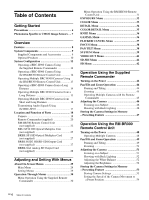 4
4 -
 5
5 -
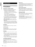 6
6 -
 7
7 -
8
-
9
-
10
-
11
-
12
-
13
-
14
-
15
-
16
-
17
-
18
-
19
-
20
-
21
-
22
-
23
-
24
-
25
-
26
-
27
-
28
-
29
-
30
-
31
-
32
-
33
-
34
-
35
-
36
-
37
-
38
-
39
-
40
-
41
-
42
-
43
-
44
-
45
-
46
-
47
-
48
-
49
-
50
-
51
-
52
-
53
-
54
-
55
-
56
-
57
-
58
-
59
-
60
-
61
-
62
-
63
-
64
-
65
-
66
-
67
-
68
-
69
-
70
-
71
-
72
-
73
-
74
-
75
-
76
-
77
-
78
-
79
-
80
-
81
-
82
-
83
-
84
-
85
-
86
-
87
-
88
-
89
-
90
-
91
-
92
-
93
-
94
-
95
-
96
-
97
-
98
-
99
-
100
-
101
-
102
-
103
-
104
-
105
-
106
-
107
-
108
-
109
-
110
-
111
-
112
-
113
-
114
-
115
-
116
-
117
-
118
-
119
-
120
-
121
-
122
-
123
-
124
-
125
-
126
-
127
-
128
-
129
-
130
-
131
-
132
-
133
-
134
-
135
-
136
-
137
-
138
-
139
-
140
-
141
-
142
-
143
-
144
-
145
-
146
-
147
-
148
-
149
-
150
-
151
-
152
-
153
-
154
-
155
-
156
-
157
-
158
-
159
-
160
-
161
-
162
-
163
-
164
-
165
-
166
-
167
-
168
-
169
-
170
-
171
-
172
-
173
-
174
-
175
-
176
-
177
-
178
-
179
-
180
-
181
-
182
-
183
-
184
-
185
-
186
-
187
-
188
-
189
-
190
-
191
-
192
-
193
-
194
-
195
-
196
-
197
-
198
-
199
-
200
-
201
-
202
-
203
-
204
-
205
-
206
-
207
-
208
-
209
-
210
-
211
-
212
-
213
-
214
-
215
-
216
-
217
-
218
-
219
-
220
-
221
-
222
-
223
-
224
-
225
-
226
-
227
-
228
-
229
-
230
-
231
-
232
-
233
-
234
-
235
-
236
-
237
-
238
-
239
-
240
-
241
-
242
-
243
-
244
-
245
-
246
-
247
-
248
-
249
-
250
-
251
-
252
-
253
-
254
-
255
-
256
-
257
-
258
-
259
-
260
-
261
-
262
-
263
-
264
-
265
-
266
-
267
-
268
-
269
-
270
-
271
 |
 |

HD Color
Video Camera
BRC-H900
4-422-803-
11
(1)
© 2012 Sony Corporation
Operating Instructions _____
GB
Mode d’emploi____________
FR
Manual de instrucciones ___
ES
Sony Corporation
Printed in Japan
Printed on recycled paper.