Sony BRCH900 Product Manual (BRC-H900 Operating Manual) - Page 58
Caution, hole on the ceiling bracket B
 |
View all Sony BRCH900 manuals
Add to My Manuals
Save this manual to your list of manuals |
Page 58 highlights
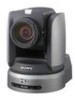
5 Attach the wire rope to the materials near the ceiling. Use an M5 (3/16 inch) hexagon socket head cap screw (not supplied). Attach the wire rope to an area independent of the area where the ceiling bracket is attached. Wire rope (supplied) Attachment materials 7 Insert the protrusions on the ceiling bracket (A) into the spaces prepared in the ceiling bracket (B) with the a hole in the front of the ceiling bracket (A) aligned with the hole on the ceiling bracket (B), and temporarily attach them by turning the ceiling bracket (A) with the camera clockwise. Ceiling M5 (3/16 inch) hexagon socket head cap screw Ceiling bracket (B) 6 Attach the wire rope to the ceiling bracket (A). Pass the wire rope through the fixing hole and attach its end to the attachment hole on the bracket using the supplied one screw (3M4 × 8). Wire rope (supplied) 3M4 × 8 (supplied) Fixing hole for wire rope Ceiling bracket (A) Ceiling hole Align. a hole Ceiling bracket (B) 1 Ceiling 2 bracket (A) 8 Secure the ceiling brackets (A) and (B) using the supplied three screws (3M3 × 8). Ceiling Installation and Connections Caution For attaching the wire rope to the bracket, use only the supplied screw. Using another screw may disable the function of the wire rope. 58 GB Installation 3M3 × 8 (supplied)
-
 1
1 -
2
-
3
-
4
-
5
-
6
-
7
-
8
-
9
-
10
-
11
-
12
-
13
-
14
-
15
-
16
-
17
-
18
-
19
-
20
-
21
-
22
-
23
-
24
-
25
-
26
-
27
-
28
-
29
-
30
-
31
-
32
-
33
-
34
-
35
-
36
-
37
-
38
-
39
-
40
-
41
-
42
-
43
-
44
-
45
-
46
-
47
-
48
-
49
-
50
-
51
-
52
-
 53
53 -
 54
54 -
 55
55 -
 56
56 -
 57
57 -
 58
58 -
 59
59 -
 60
60 -
 61
61 -
 62
62 -
 63
63 -
64
-
65
-
66
-
67
-
68
-
69
-
70
-
71
-
72
-
73
-
74
-
75
-
76
-
77
-
78
-
79
-
80
-
81
-
82
-
83
-
84
-
85
-
86
-
87
-
88
-
89
-
90
-
91
-
92
-
93
-
94
-
95
-
96
-
97
-
98
-
99
-
100
-
101
-
102
-
103
-
104
-
105
-
106
-
107
-
108
-
109
-
110
-
111
-
112
-
113
-
114
-
115
-
116
-
117
-
118
-
119
-
120
-
121
-
122
-
123
-
124
-
125
-
126
-
127
-
128
-
129
-
130
-
131
-
132
-
133
-
134
-
135
-
136
-
137
-
138
-
139
-
140
-
141
-
142
-
143
-
144
-
145
-
146
-
147
-
148
-
149
-
150
-
151
-
152
-
153
-
154
-
155
-
156
-
157
-
158
-
159
-
160
-
161
-
162
-
163
-
164
-
165
-
166
-
167
-
168
-
169
-
170
-
171
-
172
-
173
-
174
-
175
-
176
-
177
-
178
-
179
-
180
-
181
-
182
-
183
-
184
-
185
-
186
-
187
-
188
-
189
-
190
-
191
-
192
-
193
-
194
-
195
-
196
-
197
-
198
-
199
-
200
-
201
-
202
-
203
-
204
-
205
-
206
-
207
-
208
-
209
-
210
-
211
-
212
-
213
-
214
-
215
-
216
-
217
-
218
-
219
-
220
-
221
-
222
-
223
-
224
-
225
-
226
-
227
-
228
-
229
-
230
-
231
-
232
-
233
-
234
-
235
-
236
-
237
-
238
-
239
-
240
-
241
-
242
-
243
-
244
-
245
-
246
-
247
-
248
-
249
-
250
-
251
-
252
-
253
-
254
-
255
-
256
-
257
-
258
-
259
-
260
-
261
-
262
-
263
-
264
-
265
-
266
-
267
-
268
-
269
-
270
-
271
 |
 |
