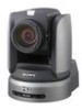
Sony BRCH900 Product Manual (BRC-H900 Operating Manual) - Page 19
Setting of the BOTTOM switches, VISCA RS-232C IN connector
 |
View all Sony BRCH900 manuals
Add to My Manuals
Save this manual to your list of manuals |
Page 19 highlights
Overview K Remote sensor This is the sensor for the supplied Remote Commander. This remote sensor does not function when IMG FLIP is set to ON in the SYSTEM menu. L HD/SD select switch Outputs an SD-SDI signal from the SDI connector when the switch is set to SD, or an HD-SDI signal from the SDI connector when the switch is set to HD. Note Set the switch before turning the camera on. M RGB/COMPONENT connector Supplies the images as an analog component (YPbPr or RGB) signal. N VISCA RS-232C IN connector Connect to the RM-BR300 Remote Control Unit (not supplied). When you connect multiple cameras, connect it to the VISCA RS-232C OUT connector of the previous camera in a daisy-chain connection. O VISCA RS-232C OUT connector When you connect multiple cameras, connect it to the VISCA RS-232C IN connector of the next camera in a daisy-chain connection. P EXT SYNC IN connector Accepts external video sync signals. Q T VIDEO connector Outputs the camera images as a composite video signal. R S VIDEO connector Outputs the camera images as an S video signal. S SDI connector Outputs the video signal from the camera as an HD/ SD-SDI signal. Supplies down-converted SD-SDI signals that conform to the SMPTE 259M serial digital interface standards, or HD-SDI signals that conform to the SMPTE 292 serial digital interface standards. Select HD-SDI or SD-SDI signals with the HD/SD select switch. T Card slot Insert the optional card, such as BRBK-HSD2, BRBK-SA1, BRBK-SF1, etc. The slot cover is attached to the camera at the factory. U DC IN 12V connector Connect the supplied AC power adaptor. Bottom ws wd wf V Ceiling bracket mounting screw holes When you install the camera to the ceiling or on a shelf, etc., in a high position, secure the supplied ceiling bracket to these holes using the supplied four screws. The four feet are attached to the holes at the factory. For installation, see "Installing the Camera in a High Position" on page 56. W Tripod screw holes (1/4-20UNC) When you install the camera to a tripod, secure the tripod to these holes. X BOTTOM switches Used for the output signal format selection, RS232C/RS-422 selection, baud rate selection, remote control signal output on/off and camera address setting. For details, see "Setting of the BOTTOM switches" on page 19. Setting of the BOTTOM switches 1 O 2 N 3 4 1 O 2 N 3 4 1 2 3 4 5 19 Location and Function of Parts GB
-
 1
1 -
2
-
3
-
4
-
5
-
6
-
7
-
8
-
9
-
10
-
11
-
12
-
13
-
 14
14 -
 15
15 -
 16
16 -
 17
17 -
 18
18 -
 19
19 -
 20
20 -
 21
21 -
 22
22 -
 23
23 -
 24
24 -
25
-
26
-
27
-
28
-
29
-
30
-
31
-
32
-
33
-
34
-
35
-
36
-
37
-
38
-
39
-
40
-
41
-
42
-
43
-
44
-
45
-
46
-
47
-
48
-
49
-
50
-
51
-
52
-
53
-
54
-
55
-
56
-
57
-
58
-
59
-
60
-
61
-
62
-
63
-
64
-
65
-
66
-
67
-
68
-
69
-
70
-
71
-
72
-
73
-
74
-
75
-
76
-
77
-
78
-
79
-
80
-
81
-
82
-
83
-
84
-
85
-
86
-
87
-
88
-
89
-
90
-
91
-
92
-
93
-
94
-
95
-
96
-
97
-
98
-
99
-
100
-
101
-
102
-
103
-
104
-
105
-
106
-
107
-
108
-
109
-
110
-
111
-
112
-
113
-
114
-
115
-
116
-
117
-
118
-
119
-
120
-
121
-
122
-
123
-
124
-
125
-
126
-
127
-
128
-
129
-
130
-
131
-
132
-
133
-
134
-
135
-
136
-
137
-
138
-
139
-
140
-
141
-
142
-
143
-
144
-
145
-
146
-
147
-
148
-
149
-
150
-
151
-
152
-
153
-
154
-
155
-
156
-
157
-
158
-
159
-
160
-
161
-
162
-
163
-
164
-
165
-
166
-
167
-
168
-
169
-
170
-
171
-
172
-
173
-
174
-
175
-
176
-
177
-
178
-
179
-
180
-
181
-
182
-
183
-
184
-
185
-
186
-
187
-
188
-
189
-
190
-
191
-
192
-
193
-
194
-
195
-
196
-
197
-
198
-
199
-
200
-
201
-
202
-
203
-
204
-
205
-
206
-
207
-
208
-
209
-
210
-
211
-
212
-
213
-
214
-
215
-
216
-
217
-
218
-
219
-
220
-
221
-
222
-
223
-
224
-
225
-
226
-
227
-
228
-
229
-
230
-
231
-
232
-
233
-
234
-
235
-
236
-
237
-
238
-
239
-
240
-
241
-
242
-
243
-
244
-
245
-
246
-
247
-
248
-
249
-
250
-
251
-
252
-
253
-
254
-
255
-
256
-
257
-
258
-
259
-
260
-
261
-
262
-
263
-
264
-
265
-
266
-
267
-
268
-
269
-
270
-
271
 |
 |
