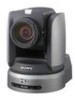
Sony BRCH900 Product Manual (BRC-H900 Operating Manual) - Page 28
BRBK-SA1 Analog SD Output Card (not supplied), VIDEO connector BNC type
 |
View all Sony BRCH900 manuals
Add to My Manuals
Save this manual to your list of manuals |
Page 28 highlights
Overview When a BRBK-HSD2 is installed in the BRU-SF10 card slot BRBK-HSD2 panel switch MONITOR connector SDI connectors 1, 2 Left position HD/ DATA MIX: ON a (HD-SDI output) Middle position HD/ DATA MIX: OFF a × (HD-SDI output) Right position SD (SD-SDI output) a/×1) a: Menu is superimposed on image ×: Menu is not superimposed on image 1) When the DATA MIX switch on the front panel of the BRU-SF10 HD Optical Multiplex Unit is set to ON, the menu display is overlapped on all images output from the card. When the DATA MIX switch is set to OFF, the menu is not displayed. BRBK-SA1 Analog SD Output Card (not supplied) 12 BRBK-SA1 VIDEO S-VIDEO 3 RGB/SYNC A T VIDEO connector (BNC type) Supplies analog composite signals. The aspect ratio can be configured in the SD menu of the camera. B S VIDEO connector (4-pin mini-DIN) Outputs S-Video signals. You can configure the aspect ratio with the SD menu of the camera. C RGB/SYNC connector (D-sub 9-pin) Supplies various analog signals such as composite video, S video, component video and RGB signals. The output signal can be selected in the SD menu of the camera. Notes • When a BRBK-SA1 Analog SD Output Card is installed in the BRC-H900 HD Color Video Camera and menu display for the camera is turned ON, the menu display is overlapped with the image. • When a BRBK-SA1 Analog SD Output Card is installed in a BRU-SF10 HD Optical Multiplex Unit on which the front panel DATA MIX switch is set to ON and menu display for the camera is turned ON, the menu display is overlapped with the image. When the DATA MIX switch is set to OFF, the menu will not be displayed on the image, even if menu display for the camera is turned ON. 28 GB Location and Function of Parts
-
 1
1 -
2
-
3
-
4
-
5
-
6
-
7
-
8
-
9
-
10
-
11
-
12
-
13
-
14
-
15
-
16
-
17
-
18
-
19
-
20
-
21
-
22
-
 23
23 -
 24
24 -
 25
25 -
 26
26 -
 27
27 -
 28
28 -
 29
29 -
 30
30 -
 31
31 -
 32
32 -
 33
33 -
34
-
35
-
36
-
37
-
38
-
39
-
40
-
41
-
42
-
43
-
44
-
45
-
46
-
47
-
48
-
49
-
50
-
51
-
52
-
53
-
54
-
55
-
56
-
57
-
58
-
59
-
60
-
61
-
62
-
63
-
64
-
65
-
66
-
67
-
68
-
69
-
70
-
71
-
72
-
73
-
74
-
75
-
76
-
77
-
78
-
79
-
80
-
81
-
82
-
83
-
84
-
85
-
86
-
87
-
88
-
89
-
90
-
91
-
92
-
93
-
94
-
95
-
96
-
97
-
98
-
99
-
100
-
101
-
102
-
103
-
104
-
105
-
106
-
107
-
108
-
109
-
110
-
111
-
112
-
113
-
114
-
115
-
116
-
117
-
118
-
119
-
120
-
121
-
122
-
123
-
124
-
125
-
126
-
127
-
128
-
129
-
130
-
131
-
132
-
133
-
134
-
135
-
136
-
137
-
138
-
139
-
140
-
141
-
142
-
143
-
144
-
145
-
146
-
147
-
148
-
149
-
150
-
151
-
152
-
153
-
154
-
155
-
156
-
157
-
158
-
159
-
160
-
161
-
162
-
163
-
164
-
165
-
166
-
167
-
168
-
169
-
170
-
171
-
172
-
173
-
174
-
175
-
176
-
177
-
178
-
179
-
180
-
181
-
182
-
183
-
184
-
185
-
186
-
187
-
188
-
189
-
190
-
191
-
192
-
193
-
194
-
195
-
196
-
197
-
198
-
199
-
200
-
201
-
202
-
203
-
204
-
205
-
206
-
207
-
208
-
209
-
210
-
211
-
212
-
213
-
214
-
215
-
216
-
217
-
218
-
219
-
220
-
221
-
222
-
223
-
224
-
225
-
226
-
227
-
228
-
229
-
230
-
231
-
232
-
233
-
234
-
235
-
236
-
237
-
238
-
239
-
240
-
241
-
242
-
243
-
244
-
245
-
246
-
247
-
248
-
249
-
250
-
251
-
252
-
253
-
254
-
255
-
256
-
257
-
258
-
259
-
260
-
261
-
262
-
263
-
264
-
265
-
266
-
267
-
268
-
269
-
270
-
271
 |
 |
