Sony BRCH900 Product Manual (BRC-H900 Operating Manual) - Page 18
Location and Function of Parts, Camera
 |
View all Sony BRCH900 manuals
Add to My Manuals
Save this manual to your list of manuals |
Page 18 highlights
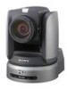
Overview Location and Function of Parts Camera Front 12 34 5 67 A Lens This is a 14-magnification optical zoom lens. Note Do not touch the part around the lens and ring outside the lens when energized. It may cause a malfunction of the camera. B Tally lamp Lights in red when a VISCA tally command is received or the camera is selected by the RMBR300 Remote Control Unit (not supplied) (depending on the setting mode). You can set the brightness of the tally lamp to HIGH, LOW, or OFF on the menu. C Remote sensor This is the sensor for the supplied Remote Commander. When you use the upper remote sensor, set IMG FLIP to ON in the SYSTEM menu (page 39). With this setting the remote sensor at the rear of the camera does not function. D Back tally lamp Lights in red when a VISCA tally command is received or the camera is selected by the RMBR300 Remote Control Unit (not supplied) (depending on the setting mode). The back tally lamp does not light when TALLY MODE in the SYSTEM menu (page 39) is set to OFF. Flashes at intervals of about 0.7 seconds if the rotating speed of the cooling fan motor reduces or if the motor stops, regardless of the on/off status of the back tally lamp. E SONY and HD nameplates Pull them out to turn them over and attach upside down if required. F POWER lamp Lights when the camera is connected to an AC outlet using the supplied AC power adaptor and AC power cord. Flashes in green when the camera receives an operation command from the supplied Remote Commander. G STANDBY lamp Lights when the camera is turned off using the Remote Commander. Rear 8 90qaqs qd 1 2 3 4 5 6 7 8 9 1 2 3 IR SELECT VISCA RS-422 OFF ON 75 R HD SD RGB/COMPONENT IN VISCA RS-232 OUT EXT SYNC IN VIDEO S VIDEO SDI OUT DC IN 12V qf qg qhqj qkqlw;wa H VISCA RS-422 connector Used for VISCA control. For connection to the VISCA RS-422 connector, see "Using the VISCA RS-422 Connector Plug" on page 89. I 75-ohm termination switch This switch is used when an external sync signal is used. Set it to OFF when this camera is in the middle of a daisy-chain connection of multiple cameras. Set it to ON when the camera is at the end of a daisy-chain connection or when nothing is connected to the EXT SYNC IN connector on the camera. J IR SELECT switch Select the camera number when you operate multiple cameras with the same Remote Commander. 18 GB Location and Function of Parts
-
 1
1 -
2
-
3
-
4
-
5
-
6
-
7
-
8
-
9
-
10
-
11
-
12
-
 13
13 -
 14
14 -
 15
15 -
 16
16 -
 17
17 -
 18
18 -
 19
19 -
 20
20 -
 21
21 -
 22
22 -
 23
23 -
24
-
25
-
26
-
27
-
28
-
29
-
30
-
31
-
32
-
33
-
34
-
35
-
36
-
37
-
38
-
39
-
40
-
41
-
42
-
43
-
44
-
45
-
46
-
47
-
48
-
49
-
50
-
51
-
52
-
53
-
54
-
55
-
56
-
57
-
58
-
59
-
60
-
61
-
62
-
63
-
64
-
65
-
66
-
67
-
68
-
69
-
70
-
71
-
72
-
73
-
74
-
75
-
76
-
77
-
78
-
79
-
80
-
81
-
82
-
83
-
84
-
85
-
86
-
87
-
88
-
89
-
90
-
91
-
92
-
93
-
94
-
95
-
96
-
97
-
98
-
99
-
100
-
101
-
102
-
103
-
104
-
105
-
106
-
107
-
108
-
109
-
110
-
111
-
112
-
113
-
114
-
115
-
116
-
117
-
118
-
119
-
120
-
121
-
122
-
123
-
124
-
125
-
126
-
127
-
128
-
129
-
130
-
131
-
132
-
133
-
134
-
135
-
136
-
137
-
138
-
139
-
140
-
141
-
142
-
143
-
144
-
145
-
146
-
147
-
148
-
149
-
150
-
151
-
152
-
153
-
154
-
155
-
156
-
157
-
158
-
159
-
160
-
161
-
162
-
163
-
164
-
165
-
166
-
167
-
168
-
169
-
170
-
171
-
172
-
173
-
174
-
175
-
176
-
177
-
178
-
179
-
180
-
181
-
182
-
183
-
184
-
185
-
186
-
187
-
188
-
189
-
190
-
191
-
192
-
193
-
194
-
195
-
196
-
197
-
198
-
199
-
200
-
201
-
202
-
203
-
204
-
205
-
206
-
207
-
208
-
209
-
210
-
211
-
212
-
213
-
214
-
215
-
216
-
217
-
218
-
219
-
220
-
221
-
222
-
223
-
224
-
225
-
226
-
227
-
228
-
229
-
230
-
231
-
232
-
233
-
234
-
235
-
236
-
237
-
238
-
239
-
240
-
241
-
242
-
243
-
244
-
245
-
246
-
247
-
248
-
249
-
250
-
251
-
252
-
253
-
254
-
255
-
256
-
257
-
258
-
259
-
260
-
261
-
262
-
263
-
264
-
265
-
266
-
267
-
268
-
269
-
270
-
271
 |
 |
