Dell PowerEdge R910 Hardware Owner's Manual
Dell PowerEdge R910 Manual
 |
View all Dell PowerEdge R910 manuals
Add to My Manuals
Save this manual to your list of manuals |
Dell PowerEdge R910 manual content summary:
- Dell PowerEdge R910 | Hardware Owner's Manual - Page 1
Dell™ PowerEdge™ R910 Hardware Owner's Manual Regulatory Model: E06S Series Regulatory Type: E06S001 - Dell PowerEdge R910 | Hardware Owner's Manual - Page 2
CAUTION: A CAUTION indicates potential damage to hardware or loss of data if instructions are not followed. WARNING: A WARNING indicates Dell Inc. is strictly forbidden. Trademarks used in this text: Dell, the DELL logo, and PowerEdge are trademarks of Dell Inc. Microsoft, Windows, and Windows Server - Dell PowerEdge R910 | Hardware Owner's Manual - Page 3
LCD Panel Features 14 Home Screen 15 Setup Menu 16 View Menu 17 Hard-Drive Indicator Patterns 18 Back-Panel Features and Indicators 19 Guidelines for Connecting External Devices 21 NIC Indicator Codes 21 Power Indicator Codes 22 LCD Status Messages 23 Viewing Status Messages 23 Removing - Dell PowerEdge R910 | Hardware Owner's Manual - Page 4
Options 65 Main Screen 65 Memory Settings Screen 67 Processor Settings Screen 68 SATA Settings Screen 69 Boot Settings Screen 69 Integrated Devices Screen 70 PCI IRQ Assignments Screen 71 Serial Communication Screen 72 Embedded Server Management Screen 73 Power Management Screen 73 System - Dell PowerEdge R910 | Hardware Owner's Manual - Page 5
Guidelines 92 Removing a Memory-Riser Blank 99 Installing a Memory-Riser Blank 100 Removing a Memory Riser 100 Installing a Memory Riser 101 Installing Memory Modules 102 Removing Memory Modules 105 Removing the Memory-Riser Guide 106 Installing the Memory-Riser Guide 107 Contents 5 - Dell PowerEdge R910 | Hardware Owner's Manual - Page 6
113 Removing an Optical Drive 113 Installing an Optical Drive 115 Cooling Fans 116 Removing a Cooling Fan 116 Installing a Cooling Fan 117 Removing the Cooling Fan Assembly 118 Installing the Cooling Fan Assembly 120 Internal USB Memory Key 120 Integrated NIC Hardware Key 123 Expansion - Dell PowerEdge R910 | Hardware Owner's Manual - Page 7
145 RAID Battery 146 Removing a RAID Battery 146 Installing the RAID Battery 147 Processors 148 Removing a Processor 148 Installing a Processor 152 Power Supplies 154 Removing a Power Supply 155 Installing a Power Supply 156 Removing the Power Supply Blank 157 Installing the Power Supply - Dell PowerEdge R910 | Hardware Owner's Manual - Page 8
157 Replacing the System Battery 157 SAS Backplane 159 Removing the SAS Backplane 159 Installing the SAS Backplane 161 Power Distribution Board 161 Removing the Power Distribution Board . . . . . 161 Replacing the Power Distribution Board . . . . . 163 Control Panel Assembly 163 Removing - Dell PowerEdge R910 | Hardware Owner's Manual - Page 9
System Battery 178 Troubleshooting Power Supplies 179 Troubleshooting System Cooling Problems 180 Troubleshooting a Fan 180 Troubleshooting System Memory 181 Troubleshooting an Internal USB Key 183 Troubleshooting an Internal SD Card 184 Troubleshooting an Optical Drive 185 Troubleshooting - Dell PowerEdge R910 | Hardware Owner's Manual - Page 10
195 Selecting Diagnostics Options 195 Viewing Information and Results 196 6 Jumpers and Connectors 197 System Board Jumper 197 System Board Connectors 198 SAS Backplane Board Connectors 200 Disabling a Forgotten Password 201 7 Getting Help 203 Contacting Dell 203 Index 205 10 Contents - Dell PowerEdge R910 | Hardware Owner's Manual - Page 11
63. Enters System Services, which opens the Lifecycle Controller BIOS Boot Manager or the UEFI Boot Manager, depending on the system's boot configuration. See "Using the System Setup Program and UEFI Boot Manager" on page 63. Starts PXE boot. Enters the iDRAC Configuration - Dell PowerEdge R910 | Hardware Owner's Manual - Page 12
Connector 1 Optical drive (optional) 2 Power-on indicator, power button Description One optional slim-line SATA DVD-ROM drive or DVD-RW drive. NOTE: DVD devices are data only. The power-on indicator lights when the system power is on. The power button controls the DC power supply output to - Dell PowerEdge R910 | Hardware Owner's Manual - Page 13
8 System identification button Description Used to troubleshoot software and device driver errors when using certain operating systems. This button can be pressed using the end of a paper clip. Use this button only if directed to do so by qualified support personnel or by the operating system - Dell PowerEdge R910 | Hardware Owner's Manual - Page 14
hard drives. NOTE: Only one SATA drive is supported on the x4 backplane. SAS and SATA hard disks on the same backplane cannot be combined into a single virtual disk. x16 backplanes do not support SATA drives. LCD Panel Features The system's LCD panel provides system information and status and error - Dell PowerEdge R910 | Hardware Owner's Manual - Page 15
more than five seconds to enter BIOS Progress mode. Home Screen The Home screen displays user-configurable information about the system. This screen or errors present. When the system is in standby mode, the LCD backlight will turn off after five minutes of inactivity if there are no error messages. - Dell PowerEdge R910 | Hardware Owner's Manual - Page 16
an option in the Setup menu, you must confirm the option before proceeding to the next action. Option DRAC Set error Set home Description Select DHCP or Static IP to configure the network mode. If Static IP is selected, the available fields are IP, Subnet (Sub), and Gateway (Gtw). Select Setup - Dell PowerEdge R910 | Hardware Owner's Manual - Page 17
of the Host, Model, or User String for the system. Displays the Asset tag or the Service tag for the system. Displays the power output of the system in BTU/hr or Watts. The display format can be configured in the Set home submenu of the Setup menu. See "Setup Menu" on page 16. Displays - Dell PowerEdge R910 | Hardware Owner's Manual - Page 18
-Status Indicator Pattern (RAID Only) Condition Blinks green two times per second Identify drive/preparing for removal Off Drive ready for insertion or removal NOTE: The drive status indicator remains off until all hard drives are initialized after system power is applied. Drives are not ready - Dell PowerEdge R910 | Hardware Owner's Manual - Page 19
(RAID Only) Condition Blinks amber four times per second Drive failed Blinks green slowly Drive rebuilding Steady green Drive online the configuration, your system may have either a 1 GbE I/O riser or a 10 Gb I/O riser. A 1 GbE I/O riser consists of four Ethernet connectors and a 10 Gb I/O - Dell PowerEdge R910 | Hardware Owner's Manual - Page 20
(7) 6 Power supplies (4) 7 System identification connector 8 System identification button Description Connects an external SD memory card for the front and back panels can be used to locate a particular system within a rack. When one of these buttons is pushed, the LCD panel on the front and - Dell PowerEdge R910 | Hardware Owner's Manual - Page 21
to the system. Guidelines for Connecting External Devices • Turn off power to the system and external devices before attaching a new external the documentation for the device specifies otherwise). • Ensure that the appropriate driver for the attached device has been installed on the system. • If - Dell PowerEdge R910 | Hardware Owner's Manual - Page 22
with the flashing indicator. Swapping the opposite power supply to make a matched pair can result in an error condition and unexpected system shutdown. To change from a High Output configuration to an Energy Smart configuration or vice versa, you must power down the system. 22 About Your System - Dell PowerEdge R910 | Hardware Owner's Manual - Page 23
For information on the SEL and configuring system management settings, see the systems management software documentation. NOTE: If your system fails to boot, press the System ID button for at least 5 seconds until an error code appears on the LCD. Record the code, then see "Getting Help" on page 203 - Dell PowerEdge R910 | Hardware Owner's Manual - Page 24
If the problem persists, see "Getting Help" on page 203. E1114 Ambient Temp exceeds allowed range. Ambient temperature has reached a point outside of the allowed range. See "Troubleshooting System Cooling Problems" on page 180. E1116 Memory disabled, temp above range. Power cycle AC. Memory has - Dell PowerEdge R910 | Hardware Owner's Manual - Page 25
a point outside of the allowed range. See "Troubleshooting System Cooling Problems" on page 180. E1210 Motherboard battery failure. Check battery. CMOS battery is missing or See "Troubleshooting the the voltage is outside of the System Battery" on allowable range. page 178. About Your System - Dell PowerEdge R910 | Hardware Owner's Manual - Page 26
"Troubleshooting Expansion Cards" on page 189. E1219 Disk Backplane power failure. Check BP power cable. Storage backplane voltage regulator has failed. Remove and reseat the backplane. If the problem persists, see "Getting Help" on page 203. E1222 CPU # VCACHE Regulator failure. Contact support - Dell PowerEdge R910 | Hardware Owner's Manual - Page 27
Insufficient standby power NICs for 10 Gb embedded NICs. disabled. Check or add PSUs. Reseat the power supplies. See "Troubleshooting Power Supplies" on page 179. If the problem persists, see "Getting Help" on page 203. E1245 CPU # VIO Regulator failure. Contact support. Processor voltage - Dell PowerEdge R910 | Hardware Owner's Manual - Page 28
E141C Unsupported Processors are in an CPU configur- unsupported configuration. ation. Check CPU or BIOS revision. Ensure that your processors match and conform to the type described in the processor technical specifications outlined in your system's Getting Started Guide. 28 About Your System - Dell PowerEdge R910 | Hardware Owner's Manual - Page 29
the problem persists, see "Getting Help" on page 203. E1610 Power Supply # (### W) missing. Check power supply. Specified power supply was removed or is missing from the system. See "Troubleshooting Power Supplies" on page 179. E1614 Power Supply Specified power supply # (### W) failed. error - Dell PowerEdge R910 | Hardware Owner's Manual - Page 30
supplies with matching wattage are installed. See the Technical Specifications outlined in your system's Getting Started Guide. E1629 Power The system configuration required > requires more power than PSU wattage. the power supplies can Check PSU and provide, even with config. throttling - Dell PowerEdge R910 | Hardware Owner's Manual - Page 31
event. Contact support. The processors and memory Remove AC power to the have been throttled to keep system for 10 seconds and system power consumption restart the system. below the maximum safe level with current power supply configuration. If the problem persists, see "Getting Help" on - Dell PowerEdge R910 | Hardware Owner's Manual - Page 32
expansion cards. If component that resides in the problem persists, see PCI configuration space at "Troubleshooting bus ##, device ##, Expansion Cards" on function ##. page 189. PCI system error on Slot #. Review & clear SEL. The system BIOS reported a Reinstall the expansion- PCI system - Dell PowerEdge R910 | Hardware Owner's Manual - Page 33
ExpansionCard Riser" on page 124. If the problem persists, the riser card or system board is faulty. See "Getting Help" on page 203. E1810 Hard drive ## The specified hard drive fault. Review experienced a fault. & clear SEL. See "Troubleshooting a Hard Drive" on page 186. About Your System 33 - Dell PowerEdge R910 | Hardware Owner's Manual - Page 34
## The specified hard drive has Information only. removed. been removed from the Check drive. system. E1813 Internal Dual The internal dual SD SD Module module card has failed. Card # failed. Check SD card. Reseat the internal dual SD module card. If the problem persists, see "Getting Help - Dell PowerEdge R910 | Hardware Owner's Manual - Page 35
not See "Troubleshooting configurable. Error detected System Memory" on during memory page 181. configuration. E2012 Memory configured Memory configured, but is unusable. but unusable. Check DIMMs. See "Troubleshooting System Memory" on page 181. E2013 BIOS unable The system BIOS failed to - Dell PowerEdge R910 | Hardware Owner's Manual - Page 36
for 10 seconds and restart the system. If the problem persists, see "Getting Help" on page 203. E2019 Parity error. Parity error. Power cycle AC. Remove AC power to the system for 10 seconds and restart the system. If the problem persists, see "Getting Help" on page 203. 36 About Your System - Dell PowerEdge R910 | Hardware Owner's Manual - Page 37
memory BIOS POST memory test test failure. failure. Check DIMMs. See "Troubleshooting System Memory" on page 181. If the problem persists, see "Getting Help" on page 203. E2020 CPU configuratio n failure. Check screen message. Processor configuration failure. Check screen for specific error - Dell PowerEdge R910 | Hardware Owner's Manual - Page 38
Code Text Causes Corrective Actions E2021 Incorrect Incorrect memory memory configuration. configur- ation. Review User Guide. Check screen for specific error messages. See "Troubleshooting System Memory" on page 181. E2022 General failure during POST. Check screen message. General - Dell PowerEdge R910 | Hardware Owner's Manual - Page 39
one half of the mirror has had too many errors. "## & ##" represents the memory module pair implicated by the BIOS. Remove AC power to the system for 10 seconds and restart the system. If the problem persists, see "Troubleshooting System Memory" on page 181. I1910 Intrusion detected. System cover - Dell PowerEdge R910 | Hardware Owner's Manual - Page 40
. If problem persists, replace the RAID battery. See "Installing the RAID Battery" on page 147. W1627 Power The system configuration required > requires more power than PSU wattage. what the power supply can Check PSU and provide. config. Turn off power to the system, reduce the hardware - Dell PowerEdge R910 | Hardware Owner's Manual - Page 41
Troubleshooting but at least one more supply Power Supplies" on can fail before the system is page 179. at risk of shutting down. If the problem persists, see "Getting Help" on page 203. NOTE: For the full name of an abbreviation or acronym used in this table, see the Glossary at support.dell BIOS - Dell PowerEdge R910 | Hardware Owner's Manual - Page 42
in a configuration that supports node interleaving. Check other system messages for additional information for possible causes. For memory configuration information, see "General Memory Module Installation Guidelines" on page 92. If the problem persists, see "Troubleshooting System Memory" on page - Dell PowerEdge R910 | Hardware Owner's Manual - Page 43
Alert! Power required exceeds PSU wattage. Check PSU and system configuration. Alert! Continuing system boot accepts the risk that system may power down without warning. The system configuration of processor(s), memory modules, and expansion cards may not be supported by the power supplies. If - Dell PowerEdge R910 | Hardware Owner's Manual - Page 44
Corrective Actions BIOS Update Remote BIOS update Attempt Failed! attempt failed. Retry the BIOS update. If problem persists, see "Getting Help" on the same cache size, number of cores and logical processors, and power rating. Ensure that the processors are properly installed. See "Processors" - Dell PowerEdge R910 | Hardware Owner's Manual - Page 45
BIOS. The management software or the OS NIC=, interface is set in NIC settings. If a problem is Management management tools. indicated, see Shared NIC= "Troubleshooting a NIC" on Error 8602 - Dell PowerEdge R910 | Hardware Owner's Manual - Page 46
If the problem persists, see "Troubleshooting a USB Device" on page 174. Keyboard fuse has Overcurrent detected at the See "Getting Help" on failed keyboard connector. page 203. Local keyboard may not work because all user accessible USB ports are disabled. If operating locally, power cycle the - Dell PowerEdge R910 | Hardware Owner's Manual - Page 47
. If the processor has bent pins, see "Getting Help" on page 203. Memory Riser disabled MemBIST error. Memory Riser disabled MemBIST timeout. Memory Riser disabled - Rank not found. Memory riser disabled - DIMM communication error The memory modules are not Replace or reseat the - Dell PowerEdge R910 | Hardware Owner's Manual - Page 48
Riser Lockstep pair DIMM disabled Please replace the DIMM or remove the lockstep pair Unsupported memory modules on slots 3 to 8. Ensure that the memory modules are installed in a valid configuration. See "General Memory Module Installation Guidelines" on page 92. 48 About Your System - Dell PowerEdge R910 | Hardware Owner's Manual - Page 49
" on page 105 and Please replace dust. "Installing Memory Modules" the DIMM(s) or Faulty memory module. on page 102. remove the Ensure that the memory lockstep pair. module connectors are clean. MemBIST error: Memory riser(s) Locstep Pair DIMM disabled. Please replace the - Dell PowerEdge R910 | Hardware Owner's Manual - Page 50
pair DIMM disabled. While mixing different rank memory modules, the lower rank memory modules are installed on slots 1 and 2 or on slots 5 and 6. Ensure that the memory modules are installed in a valid configuration. See "General Memory Module Installation Guidelines" on page 92. Please - Dell PowerEdge R910 | Hardware Owner's Manual - Page 51
pair. DellMemBIST error: Memory riser DIMM Memory riser lockstep Troubleshooting System memory modules. Memory" on page 181. Memory double word logic failure at address, read value expecting value. Faulty or improperly installed See "Troubleshooting System memory modules. Memory - Dell PowerEdge R910 | Hardware Owner's Manual - Page 52
improperly installed See "Troubleshooting System memory modules. Memory" on page 181. Memory set to minimum frequency. The memory frequency may If power conservation. messages for possible causes. The current memory Ensure that your memory configuration may support configuration supports - Dell PowerEdge R910 | Hardware Owner's Manual - Page 53
key installed. Use a bootable USB key, CD, or hard drive. If the problem persists, see "Troubleshooting an Internal USB Key" on page 183, "Troubleshooting a USB Device" on page 174, "Troubleshooting an Optical Drive" on page 185, and "Troubleshooting a Hard Drive" on page 186. See "Using the System - Dell PowerEdge R910 | Hardware Owner's Manual - Page 54
specified slot number. See Link Width is x, slot. "Troubleshooting Expansion Actual Link Width Cards" on page 189. If the is y. problem persists, see "Getting Help" on page 203. Plug & Play Configuration Error. Error encountered in initializing PCIe device; faulty system board. Install - Dell PowerEdge R910 | Hardware Owner's Manual - Page 55
or SAS backplane cables are properly connected. See "Troubleshooting a USB Device" on page 174 or "Troubleshooting a Hard Drive" on page 186 for the appropriate drive(s) installed in your system. Shutdown failure General system error. See "Getting Help" on page 203. The amount of Memory has been - Dell PowerEdge R910 | Hardware Owner's Manual - Page 56
problem persists, replace the system battery. See "System Battery" on page 157. Timer chip Faulty system board. counter 2 failed. See "Getting Help" on page 203. TPM or TCM configuration after a TPM or TCM configuration command has been entered. User interaction is required to proceed. Enter I - Dell PowerEdge R910 | Hardware Owner's Manual - Page 57
. support.dell.com. See the iDRAC6 user's guide for instructions on performing a field replacement of the flash memory. Unexpected interrupt in protected mode. Improperly seated memory modules or faulty keyboard/mouse controller chip. Reseat the memory modules. See "Troubleshooting System - Dell PowerEdge R910 | Hardware Owner's Manual - Page 58
. Warning! No micro Micro code update failed. code update loaded for processor n. Update the BIOS firmware. See "Getting Help" on page 203. Warning! Power required exceeds PSU wattage. Check PSU and system configuration. Warning! Performance degraded. CPU and memory set to minimum frequencies to - Dell PowerEdge R910 | Hardware Owner's Manual - Page 59
the problem persists, see "Troubleshooting System Memory" on page 181. Write fault Write fault on selected drive. Faulty USB device, USB Replace the USB medium or medium, optical drive device. Ensure that the USB, assembly, hard drive, or hard- SAS backplane, or SATA drive subsystem. cables - Dell PowerEdge R910 | Hardware Owner's Manual - Page 60
this document or as a separate document. • The rack documentation included with your rack solution describes how to install your system into a rack. • The Getting Started Guide provides an overview of system features, setting up your system, and technical specifications. 60 About Your System - Dell PowerEdge R910 | Hardware Owner's Manual - Page 61
and tools for configuring and managing your system, including those pertaining to the operating system, system management software, system updates, and system components that you purchased with your system. NOTE: Always check for updates on support.dell.com/manuals and read the updates first because - Dell PowerEdge R910 | Hardware Owner's Manual - Page 62
62 About Your System - Dell PowerEdge R910 | Hardware Owner's Manual - Page 63
manage your system hardware and specify BIOS-level options. From the System Setup program, you can: • Change the NVRAM settings after you add or remove hardware • View the system hardware configuration • Enable or disable integrated devices • Set performance and power management thresholds • Manage - Dell PowerEdge R910 | Hardware Owner's Manual - Page 64
for correcting errors. NOTE: After installing a memory upgrade, it is normal for your system to display a message the first time you start your the System Setup program and restarts the system if any changes were made. Displays the System Setup program's help file. NOTE: For most of the - Dell PowerEdge R910 | Hardware Owner's Manual - Page 65
for the System Setup program change based on the system configuration. NOTE: The System Setup program defaults are listed under their respective options in the following sections, where applicable. Option System Time System Date Memory Settings Processor Settings Description Sets the time on the - Dell PowerEdge R910 | Hardware Owner's Manual - Page 66
and any installed expansion card that requires an IRQ. See "PCI IRQ Server Management Screen" on page 73. Enables you to manage power usage of the processor(s), fans, and memory modules with preconfigured or customized settings. See "Power Management Screen" on page 73. Displays a screen to configure - Dell PowerEdge R910 | Hardware Owner's Manual - Page 67
Spare Mode, and Disabled. If this field is Enabled, memory interleaving is supported if a symmetric memory configuration is installed. If Disabled, the system supports Non-Uniform Memory architecture (NUMA) (asymmetric) memory configurations. Using the System Setup Program and UEFI Boot Manager 67 - Dell PowerEdge R910 | Hardware Owner's Manual - Page 68
the hardware prefetcher. Execute Disable (Enabled default) Enables or disables Execute Disable Memory Protection Technology. Number of Cores per Processor (All default) If set to All, the maximum number of cores in each processor is enabled. Turbo Mode If Turbo Boost Technology is supported by - Dell PowerEdge R910 | Hardware Owner's Manual - Page 69
Boot Mode (BIOS default) Boot Sequence Hard-Disk Drive Sequence Description CAUTION: Switching the boot mode could prevent the system from booting if the operating system was not installed in the same boot mode. If the system operating system supports Unified Extensible Firmware Interface, you - Dell PowerEdge R910 | Hardware Owner's Manual - Page 70
the internal SD card slot. A device installed in the internal SD card slot will automatically emulate a hard drive. If you install a device in this slot that is configured as a removable diskette drive, you must manually set the emulation type to Floppy. If this field is enabled and the system has - Dell PowerEdge R910 | Hardware Owner's Manual - Page 71
feature is usable only with operating systems that support WDAT implementations of the Advanced Configuration and Power Interface (ACPI) 3.0b specification. Enables or disables the I/O Acceleration Technology feature. Enables or disables BIOS support for the integrated video controller. NOTE: This - Dell PowerEdge R910 | Hardware Owner's Manual - Page 72
for Serial Over LAN (SOL). To use console redirection by SOL, configure the same port address for console redirection and the serial device. Failsafe default) Displays the failsafe baud rate used for console redirection. BIOS attempts to determine the baud rate automatically. This failsafe baud - Dell PowerEdge R910 | Hardware Owner's Manual - Page 73
Performance. For all but the Custom setting, the BIOS pre-configures the power settings on this screen as follows: • OS Control sets the CPU power to OS DBPM, the fan power to Minimum Power, and the memory power to Maximum Performance. In this setting, all processor performance information is - Dell PowerEdge R910 | Hardware Owner's Manual - Page 74
Power and Performance Management Memory Power and Performance Management Description Options are OS DBPM, System DBPM, Maximum Performance, or Minimum Power. Options are Maximum Performance or Minimum Power. Options are Maximum changed or disabled at system start-up. See "Using the System Password" - Dell PowerEdge R910 | Hardware Owner's Manual - Page 75
in the TPM. This option prevents booting to the operating system and results in data loss if the encryption keys cannot be restored. Back up the TPM keys prior is set to Off. If Enabled, the power button can turn the system's power off and on. On an ACPI-compliant operating system, the system - Dell PowerEdge R910 | Hardware Owner's Manual - Page 76
qualified support power state. On turns on the system after power is restored. Off allows the system to remain off after power is restored. AC Power Recovery Delay Determines when the system restarts after power example, Microsoft® Windows Server® 2008 x64 version) from the BIOS boot mode - Dell PowerEdge R910 | Hardware Owner's Manual - Page 77
Manager Navigation Keys Keys Up arrow Down arrow Spacebar, Action Moves to and highlights the previous field. Moves to and options> UEFI Boot Settings Description The system attempts to boot to devices starting with the first item in the boot order. If the boot attempt - Dell PowerEdge R910 | Hardware Owner's Manual - Page 78
Option System Utilities Description Enables you to access the System Setup program, System Services (Unified Server Configurator [USC]), Diagnostics, and BIOS-level boot options. UEFI Boot Settings Screen Option Add Boot Option Delete Boot Option Enable/Disable Boot Option Change Boot Order One- - Dell PowerEdge R910 | Hardware Owner's Manual - Page 79
on your system. CAUTION: Anyone can access the data stored on your system if the system is running and unattended. Using the System Password When a system password is assigned, the system prompts for the system password after the system starts and only those with the password have full use of the - Dell PowerEdge R910 | Hardware Owner's Manual - Page 80
The password assignment is not case-sensitive. Certain key combinations are invalid and if you enter one, the the correct password. After the third unsuccessful attempt, the system displays an error message that the system has halted and will shut down. Even after you shut down and restart the - Dell PowerEdge R910 | Hardware Owner's Manual - Page 81
your password. As you type, placeholders appear in the field. The password assignment is not case-sensitive. Certain key combinations are invalid and if you enter one, the system beeps. To immediately (restarting the system is not required). Using the System Setup Program and UEFI Boot Manager 81 - Dell PowerEdge R910 | Hardware Owner's Manual - Page 82
. For more information about setting up the Lifecycle Controller, configuring hardware and firmware, and deploying the operating system, see the Lifecycle Controller documentation on the Dell Support website at support.dell.com/manuals. 82 Using the System Setup Program and UEFI Boot Manager - Dell PowerEdge R910 | Hardware Owner's Manual - Page 83
for the managed server. The iDRAC Configuration Utility provides the power state or the system's operating system • Provides text console redirection for system setup, text-based utilities, and operating system consoles In addition, the iDRAC Configuration Utility enables you to: • Configure - Dell PowerEdge R910 | Hardware Owner's Manual - Page 84
84 Using the System Setup Program and UEFI Boot Manager - Dell PowerEdge R910 | Hardware Owner's Manual - Page 85
only perform troubleshooting and simple repairs as authorized in your product documentation, or as directed by the online or telephone service and support team. Damage due to servicing that is not authorized by Dell is not covered by your warranty. Read and follow the safety instructions that came - Dell PowerEdge R910 | Hardware Owner's Manual - Page 86
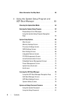
11 10 1 optical drive (optional) 3 memory risers (up to 8) 5 power supply bays (4) 7 I/O card 9 cooling fan assembly 11 system identification panel 2 control panel display 4 cooling fans (up to 6) 6 PCIe expansion card 8 integrated storage controller card 10 hard drives (up to 16) 86 Installing - Dell PowerEdge R910 | Hardware Owner's Manual - Page 87
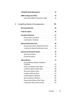
and Installing the Front Bezel 3 2 1 1 release latch 3 front bezel 2 key lock Installing the Front Bezel 1 Hook the right end of the bezel onto the chassis. 2 Fit the free end of the bezel onto the system and secure the bezel with the keylock. See Figure 3-2. Installing System Components 87 - Dell PowerEdge R910 | Hardware Owner's Manual - Page 88
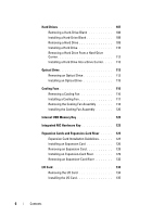
Bezel" on page 87. 2 Pull the system identification panel out of its slot in the chassis, until it is in the lock position. See Figure 3-3. The system identification panel is located above the hard drive slot 8. 3 To release the left portion of the system identification panel, pull the panel to - Dell PowerEdge R910 | Hardware Owner's Manual - Page 89
only perform troubleshooting and simple repairs as authorized in your product documentation, or as directed by the online or telephone service and support team. Damage due to servicing that is not authorized by Dell is not covered by your warranty. Read and follow the safety instructions that came - Dell PowerEdge R910 | Hardware Owner's Manual - Page 90
Opening and Closing the System 1 2 3 1 latch 3 cover 2 latch release lock Closing the System 1 Place the cover onto the chassis and offset it slightly toward the back of the system, so that the chassis hooks on the back edge of the cover fit over the corresponding slots on the back edge of the - Dell PowerEdge R910 | Hardware Owner's Manual - Page 91
channel is marked with white release levers. The maximum memory that is supported on your system varies according to the sizes of memory modules being used. Single-rank, dual-rank, and quadrank RDIMMs of sizes 1 GB, 2 GB, 4 GB, 8 GB, and 16 GB are supported for a total of up to 1 TB. NOTE: Depending - Dell PowerEdge R910 | Hardware Owner's Manual - Page 92
your system from starting and producing any video output. • All populated memory risers must have identical configurations. • The memory configuration for each processor must be identical for optimal performance. • Memory modules of different sizes can be mixed (for example, 2 GB and 4 GB), but all - Dell PowerEdge R910 | Hardware Owner's Manual - Page 93
Table 3-1. Memory Configurations (Dual Processor) CPU 1 Memory mode Riser A (memory capacity in GB) Riser B (memory capacity in GB) Total memory (per processor) 1 2 3 4 1 2 3 4 / total system 5 6 7 8 5 6 7 8 memory Power optimized 4 / 8 2 2 Not installed 8 / 16 4 4 Not - Dell PowerEdge R910 | Hardware Owner's Manual - Page 94
CPU 2 Memory mode Riser A (memory capacity in GB) Riser B (memory capacity in GB) Total memory 1 2 3 4 1 2 3 4 (per processor) 5 6 7 8 5 6 7 8 / total system memory Power optimized 4 / 8 2 2 Not installed 8 / 16 4 4 Not installed 16 / 32 4 4 4 4 Not installed 32 - Dell PowerEdge R910 | Hardware Owner's Manual - Page 95
Table 3-2. Memory Configurations (Four Processors) CPU 1 Memory mode Total Riser A (memory capacity in GB) memory (per processor) / 1 2 3 4 total system 5 6 7 8 memory Riser B (memory capacity in GB) 1 2 3 4 5 6 7 8 Power 4 / 16 2 2 optimized 8 / 32 4 4 Not installed - Dell PowerEdge R910 | Hardware Owner's Manual - Page 96
memory capacity in GB) memory (per processor) / 1 2 3 4 total system 5 6 7 8 memory Riser B (memory capacity in GB) 1 2 3 4 5 6 7 8 Power 4 4 4 4 4 4 4 4 48 / 192 8 8 4 4 8 8 4 4 Power and performance optimized 2 / 8 1 1 Not installed 64 / 256 4 4 4 4 4 4 - Dell PowerEdge R910 | Hardware Owner's Manual - Page 97
memory capacity in GB) memory (per processor) / 1 2 3 4 total system 5 6 7 8 memory Riser B (memory capacity in GB) 1 2 3 4 5 6 7 8 Power 4 4 4 4 4 4 4 4 48 / 192 8 8 4 4 8 8 4 4 Power and performance optimized 2 / 8 1 1 Not installed 64 / 256 4 4 4 4 4 4 - Dell PowerEdge R910 | Hardware Owner's Manual - Page 98
CPU 4 Memory mode Total Riser A (memory capacity in GB) memory (per processor) / 1 2 3 total system 5 6 4 7 8 memory Riser B (memory capacity in GB) 1 2 3 4 5 6 7 8 Power optimized 4 / 16 8 / 32 2 2 4 4 Not installed Not installed 16 / 64 4 4 4 4 Not installed 32 - Dell PowerEdge R910 | Hardware Owner's Manual - Page 99
only perform troubleshooting and simple repairs as authorized in your product documentation, or as directed by the online or telephone service and support team. Damage due to servicing that is not authorized by Dell is not covered by your warranty. Read and follow the safety instructions that came - Dell PowerEdge R910 | Hardware Owner's Manual - Page 100
by the online or telephone service and support team. Damage due to servicing that is not authorized by Dell is not covered by your warranty. Read and follow the safety instructions that came with the product. 1 Align the memory-riser blank with the slots on the memory-riser guide and the cooling fan - Dell PowerEdge R910 | Hardware Owner's Manual - Page 101
Figure 3-7. Removing and Installing a Memory Riser 1 2 3 5 4 1 handle 3 release button 5 memory-riser connector 2 memory riser 4 card guide Installing a Memory Riser 1 Turn off the system, including any attached peripherals, and disconnect the system from the electrical outlet. 2 Open the system - Dell PowerEdge R910 | Hardware Owner's Manual - Page 102
only perform troubleshooting and simple repairs as authorized in your product documentation, or as directed by the online or telephone service and support team. Damage due to servicing that is not authorized by Dell is not covered by your warranty. Read and follow the safety instructions that came - Dell PowerEdge R910 | Hardware Owner's Manual - Page 103
Figure 3-8. Removing and Installing the Memory Module Cover 1 2 1 release tab 2 memory module cover CAUTION: Handle each memory module only on either card edge, making sure not to touch the middle of the memory module. 5 Press the ejectors on the memory module socket down and out, as shown in - Dell PowerEdge R910 | Hardware Owner's Manual - Page 104
modules installed. 8 Repeat step 5 through step 7 of this procedure to install the remaining memory modules. See Table 3-1 and Table 3-2. 9 Close the memory module cover. 10 Install the memory risers. See "Installing a Memory Riser" on page 101. 11 Close the system. See "Closing the System" on page - Dell PowerEdge R910 | Hardware Owner's Manual - Page 105
only perform troubleshooting and simple repairs as authorized in your product documentation, or as directed by the online or telephone service and support team. Damage due to servicing that is not authorized by Dell is not covered by your warranty. Read and follow the safety instructions that came - Dell PowerEdge R910 | Hardware Owner's Manual - Page 106
101. 8 Close the system. See "Closing the System" on page 90. 9 Reconnect the system and peripherals to their power sources, and turn them on. Removing the Memory-Riser Guide 1 Turn off the system, including any attached peripherals, and disconnect the system from the electrical outlet. 2 Open the - Dell PowerEdge R910 | Hardware Owner's Manual - Page 107
"Installing a Memory- Riser Blank" on page 100. 5 Close the system. See "Closing the System" on page 90. 6 Reconnect the system and peripherals to their power sources, and turn them on. Hard Drives All drives connect to the system board through the SAS/SATA backplane board. Hard drives are supplied - Dell PowerEdge R910 | Hardware Owner's Manual - Page 108
" on page 87. 3 Press the release tab and slide the drive blank out until it is free of the drive bay. See Figure 3-11. Figure 3-11. Removing or Installing a Hard-Drive Blank 1 2 1 hard-drive blank 2 release tab Installing a Hard-Drive Blank 1 If installed, remove the front bezel. See "Removing - Dell PowerEdge R910 | Hardware Owner's Manual - Page 109
activity/fault indicator flashes as the drive is powered down. When the drive indicators are off, the drive is ready for removal. 3 Open the drive carrier release handle to release the drive. See Figure 3-12. 4 Slide the hard drive out until it is free of the drive bay. CAUTION: To maintain proper - Dell PowerEdge R910 | Hardware Owner's Manual - Page 110
Drive 1 2 1 release button 2 hard drive carrier handle Installing a Hard Drive CAUTION: Use only hard drives that have been tested and approved for use with the SAS/SATA backplane. CAUTION: When installing a hard drive, ensure that the adjacent drives are fully installed. Inserting a hard-drive - Dell PowerEdge R910 | Hardware Owner's Manual - Page 111
you are upgrading your system to a 16-hard-drive configuration, turn off the system and remove all the chassis blanks. To remove the chassis blank, press down and push the blue release tab toward the front of the system. See Figure 3-13. 3 Press the button on the front of the drive carrier and open - Dell PowerEdge R910 | Hardware Owner's Manual - Page 112
a Hard Drive From a Hard-Drive Carrier Remove the screws from the slide rails on the hard-drive carrier and separate the hard drive from the carrier. See Figure 3-14. Figure 3-14. Removing or Installing a Hot-Swap Hard Drive Into a Drive Carrier 4 1 2 3 1 screws (4) 3 SAS/SATA screw hole 2 drive - Dell PowerEdge R910 | Hardware Owner's Manual - Page 113
only perform troubleshooting and simple repairs as authorized in your product documentation, or as directed by the online or telephone service and support team. Damage due to servicing that is not authorized by Dell is not covered by your warranty. Read and follow the safety instructions that came - Dell PowerEdge R910 | Hardware Owner's Manual - Page 114
on, including any attached peripherals. 12 If applicable, install the front bezel. See "Installing the Front Bezel" on page 87. Figure 3-15. Removing the Optical Drive 2 3 1 1 optical drive 3 release tab 2 power/data cable 114 Installing System Components - Dell PowerEdge R910 | Hardware Owner's Manual - Page 115
only perform troubleshooting and simple repairs as authorized in your product documentation, or as directed by the online or telephone service and support team. Damage due to servicing that is not authorized by Dell is not covered by your warranty. Read and follow the safety instructions that came - Dell PowerEdge R910 | Hardware Owner's Manual - Page 116
only perform troubleshooting and simple repairs as authorized in your product documentation, or as directed by the online or telephone service and support team. Damage due to servicing that is not authorized by Dell is not covered by your warranty. Read and follow the safety instructions that came - Dell PowerEdge R910 | Hardware Owner's Manual - Page 117
only perform troubleshooting and simple repairs as authorized in your product documentation, or as directed by the online or telephone service and support team. Damage due to servicing that is not authorized by Dell is not covered by your warranty. Read and follow the safety instructions that came - Dell PowerEdge R910 | Hardware Owner's Manual - Page 118
only perform troubleshooting and simple repairs as authorized in your product documentation, or as directed by the online or telephone service and support team. Damage due to servicing that is not authorized by Dell is not covered by your warranty. Read and follow the safety instructions that came - Dell PowerEdge R910 | Hardware Owner's Manual - Page 119
Figure 3-17. Removing and Installing the Fan Assembly 1 2 3 1 handles (2) 3 release tabs (2) 2 cooling fan assembly Installing System Components 119 - Dell PowerEdge R910 | Hardware Owner's Manual - Page 120
only perform troubleshooting and simple repairs as authorized in your product documentation, or as directed by the online or telephone service and support team. Damage due to servicing that is not authorized by Dell is not covered by your warranty. Read and follow the safety instructions that came - Dell PowerEdge R910 | Hardware Owner's Manual - Page 121
only perform troubleshooting and simple repairs as authorized in your product documentation, or as directed by the online or telephone service and support team. Damage due to servicing that is not authorized by Dell is not covered by your warranty. Read and follow the safety instructions that came - Dell PowerEdge R910 | Hardware Owner's Manual - Page 122
Figure 3-18. Removing and Installing a USB Memory Key 1 2 1 USB memory key 2 USB memory key connector 122 Installing System Components - Dell PowerEdge R910 | Hardware Owner's Manual - Page 123
only perform troubleshooting and simple repairs as authorized in your product documentation, or as directed by the online or telephone service and support team. Damage due to servicing that is not authorized by Dell is not covered by your warranty. Read and follow the safety instructions that came - Dell PowerEdge R910 | Hardware Owner's Manual - Page 124
Figure 3-19. Removing or Installing a NIC Hardware Key 1 2 1 NIC hardware key 2 iSCSI_KEY connector 5 Close the system. See • The expansion-card slot is not hot-swappable. • PCI Express Generation 2 slots support both PCI Express Generation 1 and PCI Express Generation 2 cards. However, using a - Dell PowerEdge R910 | Hardware Owner's Manual - Page 125
on slot 5 and Generation 2 expansion cards are supported in the slots 1, 2, 3, 4, 6, and 7. • Slot 7 can be expanded to four additional PCIe x4 Generation 2 low profile slots using an optional PCIe expansion riser. • Table 3-3 provides a guide for installing expansion cards to ensure proper cooling - Dell PowerEdge R910 | Hardware Owner's Manual - Page 126
only perform troubleshooting and simple repairs as authorized in your product documentation, or as directed by the online or telephone service and support team. Damage due to servicing that is not authorized by Dell is not covered by your warranty. Read and follow the safety instructions that came - Dell PowerEdge R910 | Hardware Owner's Manual - Page 127
Figure 3-20. Installing or Removing an Expansion Card 1 2 3 4 1 expansion-card latch 3 expansion card 2 screw 4 expansion-card connector Installing System Components 127 - Dell PowerEdge R910 | Hardware Owner's Manual - Page 128
only perform troubleshooting and simple repairs as authorized in your product documentation, or as directed by the online or telephone service and support team. Damage due to servicing that is not authorized by Dell is not covered by your warranty. Read and follow the safety instructions that came - Dell PowerEdge R910 | Hardware Owner's Manual - Page 129
only perform troubleshooting and simple repairs as authorized in your product documentation, or as directed by the online or telephone service and support team. Damage due to servicing that is not authorized by Dell is not covered by your warranty. Read and follow the safety instructions that came - Dell PowerEdge R910 | Hardware Owner's Manual - Page 130
Figure 3-21. Removing and Installing the Panel 1 2 1 latch 2 panel 130 Installing System Components - Dell PowerEdge R910 | Hardware Owner's Manual - Page 131
Figure 3-22. Removing and Installing an Expansion Card in an Expansion-Card Riser 4 3 2 1 1 expansion-card riser 3 tabs (2) 2 expansion card 4 expansion-card latch Installing System Components 131 - Dell PowerEdge R910 | Hardware Owner's Manual - Page 132
Figure 3-23. Removing and Installing an Expansion-Card Riser 1 2 3 1 release tabs (2) 3 expansion-card riser connector 2 expansion-card riser 132 Installing System Components - Dell PowerEdge R910 | Hardware Owner's Manual - Page 133
only perform troubleshooting and simple repairs as authorized in your product documentation, or as directed by the online or telephone service and support team. Damage due to servicing that is not authorized by Dell is not covered by your warranty. Read and follow the safety instructions that came - Dell PowerEdge R910 | Hardware Owner's Manual - Page 134
only perform troubleshooting and simple repairs as authorized in your product documentation, or as directed by the online or telephone service and support team. Damage due to servicing that is not authorized by Dell is not covered by your warranty. Read and follow the safety instructions that came - Dell PowerEdge R910 | Hardware Owner's Manual - Page 135
Figure 3-24. Removing and Installing the I/O Card 1 2 1 I/O card 2 I/O card connector Installing the I/O Card 1 If applicable install the iDRAC6 Enterprise card. See "Installing an iDRAC6 Enterprise Card" on page 136. 2 If applicable, install the internal dual SD module. See "Installing the - Dell PowerEdge R910 | Hardware Owner's Manual - Page 136
only perform troubleshooting and simple repairs as authorized in your product documentation, or as directed by the online or telephone service and support team. Damage due to servicing that is not authorized by Dell is not covered by your warranty. Read and follow the safety instructions that came - Dell PowerEdge R910 | Hardware Owner's Manual - Page 137
I/O card. See "Installing the I/O Card" on page 135. 7 Close the system. See "Closing the System" on page 90. 8 Reconnect the system and peripherals to their power sources, and turn them on. Installing System Components 137 - Dell PowerEdge R910 | Hardware Owner's Manual - Page 138
only perform troubleshooting and simple repairs as authorized in your product documentation, or as directed by the online or telephone service and support team. Damage due to servicing that is not authorized by Dell is not covered by your warranty. Read and follow the safety instructions that came - Dell PowerEdge R910 | Hardware Owner's Manual - Page 139
contact-pin end of the troubleshooting and simple repairs as authorized in your product documentation, or as directed by the online or telephone service and support team. Damage due to servicing that is not authorized by Dell is not covered by your warranty. Read and follow the safety instructions - Dell PowerEdge R910 | Hardware Owner's Manual - Page 140
"Installing the I/O Card" on page 135. 8 Close the system. See "Closing the System" on page 90. 9 Reconnect the system and peripherals to their power sources, and turn them on. Figure 3-26. Removing and Installing the Internal Dual SD Module 3 4 2 1 1 retention standoff posts (3) 3 SD module cable - Dell PowerEdge R910 | Hardware Owner's Manual - Page 141
only perform troubleshooting and simple repairs as authorized in your product documentation, or as directed by the online or telephone service and support team. Damage due to servicing that is not authorized by Dell is not covered by your warranty. Read and follow the safety instructions that came - Dell PowerEdge R910 | Hardware Owner's Manual - Page 142
troubleshooting and simple repairs as authorized in your product documentation, or as directed by the online or telephone service and support team. Damage due to servicing that is not authorized by Dell is not covered by your warranty. Read and follow the safety instructions contact-pin end of the - Dell PowerEdge R910 | Hardware Owner's Manual - Page 143
set up the hard drives in RAID configurations as supported by the version of the storage controller included with your system. Removing the Integrated Storage Controller Card CAUTION: Many repairs may only be done by a certified service technician. You should only perform troubleshooting and simple - Dell PowerEdge R910 | Hardware Owner's Manual - Page 144
Figure 3-27. Installing the Integrated Storage Controller Card 1 2 3 5 4 1 battery cable 3 integrated storage controller card 5 clip 2 SAS data cables (2) 4 integrated storage controller card connector 144 Installing System Components - Dell PowerEdge R910 | Hardware Owner's Manual - Page 145
only perform troubleshooting and simple repairs as authorized in your product documentation, or as directed by the online or telephone service and support team. Damage due to servicing that is not authorized by Dell is not covered by your warranty. Read and follow the safety instructions that came - Dell PowerEdge R910 | Hardware Owner's Manual - Page 146
controller card. Removing a RAID Battery CAUTION: Many repairs may only be done by a certified service technician. You should only perform troubleshooting and simple repairs as authorized in your product documentation, or as directed by the online or telephone service and support team. Damage due to - Dell PowerEdge R910 | Hardware Owner's Manual - Page 147
and support team. Damage due to servicing that is not authorized by Dell is not covered by your warranty. Read and follow the safety instructions that came with the product. 1 Connect the battery cable to the integrated storage controller card. 2 Route the battery cable/SAS A cable along the chassis - Dell PowerEdge R910 | Hardware Owner's Manual - Page 148
your warranty. Read and follow the safety instructions that came with the product. 1 Prior to upgrading your system, download the latest system BIOS version from support.dell.com and follow the instructions included in the compressed download file to install the update on your system. 2 Turn off the - Dell PowerEdge R910 | Hardware Owner's Manual - Page 149
the Cooling Fan Assembly" on page 118. WARNING: The heat sink and processor are hot to touch for some time after the system has been powered down. Allow the heat sink and processor to cool before handling them. CAUTION: Never remove the heat sink from a processor unless you intend to remove - Dell PowerEdge R910 | Hardware Owner's Manual - Page 150
Figure 3-29. Installing and Removing the Heat Sink 2 1 1 release levers (2) 2 heat sink CAUTION: The processor is held in its socket under strong pressure. Be aware that the release lever can spring up suddenly if not firmly grasped. 11 Position your thumb firmly over the processor socket- - Dell PowerEdge R910 | Hardware Owner's Manual - Page 151
CAUTION: Be careful not to bend any of the pins on the ZIF socket when removing the processor. Bending the pins can permanently damage the system board. 13 Carefully lift the processor out of the socket and leave the release lever up so that the socket is ready for the new processor. After removing - Dell PowerEdge R910 | Hardware Owner's Manual - Page 152
only perform troubleshooting and simple repairs as authorized in your product documentation, or as directed by the online or telephone service and support team. Damage due to servicing that is not authorized by Dell is not covered by your warranty. Read and follow the safety instructions that came - Dell PowerEdge R910 | Hardware Owner's Manual - Page 153
heat-sink release levers. See Figure 3-29. 15 Install the cooling fan assembly. See "Installing the Cooling Fan Assembly" on page 120. 16 Install the memory risers. See "Installing a Memory Riser" on page 101. Installing System Components 153 - Dell PowerEdge R910 | Hardware Owner's Manual - Page 154
supports the following power supply modules: • 1100 W (high output power supply) • 750 W (energy smart power supply) When a 10 Gb I/O card is installed, the system must have at least two power supplies connected to an A/C power supply. The system requires two power supplies to provide standby power - Dell PowerEdge R910 | Hardware Owner's Manual - Page 155
the system operates with a limited load. System Configuration Non-redundant configuration Redundant configuration Non-redundant configuration Redundant configuration Redundant configuration Removing a Power Supply CAUTION: The system requires one power supply to operate the system normally. On - Dell PowerEdge R910 | Hardware Owner's Manual - Page 156
have the same maximum output power. NOTE: The maximum output power (shown in watts) is listed on the power supply label. 2 If applicable, remove the power supply blank. See "Removing the Power Supply Blank" on page 157. 3 Slide the new power supply into the chassis until the power supply is fully - Dell PowerEdge R910 | Hardware Owner's Manual - Page 157
only perform troubleshooting and simple repairs as authorized in your product documentation, or as directed by the online or telephone service and support team. Damage due to servicing that is not authorized by Dell is not covered by your warranty. Read and follow the safety instructions that came - Dell PowerEdge R910 | Hardware Owner's Manual - Page 158
. See "System Board Connectors" on page 198. CAUTION: To avoid damage to the battery connector, you must firmly support the connector while installing or removing a battery. 4 To remove the battery, support the battery connector by pressing down firmly on the positive side of the connector. 5 Press - Dell PowerEdge R910 | Hardware Owner's Manual - Page 159
all hard drives. See "Removing a Hard Drive" on page 109. 5 If applicable, remove the memory-riser blanks. See "Removing a Memory- Riser Blank" on page 99. 6 Remove the memory risers. See "Removing a Memory Riser" on page 100. 7 Disconnect the SAS data cable(s) and power cable from the backplane - Dell PowerEdge R910 | Hardware Owner's Manual - Page 160
. 10 Pull the backplane away from the front of the system until the securing slots are free from the tabs on the chassis. Figure 3-34. Removing and Installing a SAS Backplane 1 2 3 5 4 1 SAS backplane 3 release pins (2) 5 SAS cables (2) 2 power cable 4 chassis tabs 160 Installing System - Dell PowerEdge R910 | Hardware Owner's Manual - Page 161
and power cable to the backplane. 4 If applicable, connect the optical drive power/data cable. 5 Install the memory risers. See "Installing a Memory Riser" on page 101. 6 If applicable, install the memory-riser blanks. See "Installing a Memory- Riser Blank" on page 100. 7 Install the hard drives in - Dell PowerEdge R910 | Hardware Owner's Manual - Page 162
. See "Removing a Memory Riser" on page 100. 6 Remove the cooling fan assembly. See "Removing the Cooling Fan Assembly" on page 118. 7 Slide the board upwards and pull the board toward the front of the system until the tabs on the board are free from the securing slots on the chassis. See Figure - Dell PowerEdge R910 | Hardware Owner's Manual - Page 163
only perform troubleshooting and simple repairs as authorized in your product documentation, or as directed by the online or telephone service and support team. Damage due to servicing that is not authorized by Dell is not covered by your warranty. Read and follow the safety instructions that came - Dell PowerEdge R910 | Hardware Owner's Manual - Page 164
only perform troubleshooting and simple repairs as authorized in your product documentation, or as directed by the online or telephone service and support team. Damage due to servicing that is not authorized by Dell is not covered by your warranty. Read and follow the safety instructions that came - Dell PowerEdge R910 | Hardware Owner's Manual - Page 165
Figure 3-36. Removing or Installing the Control Panel Assembly 1 2 3 4 5 1 T8 Torx screw 3 control panel board 5 control panel cable 7 display module 6 7 2 T10 Torx screws (3) 4 USB cable 6 display module cable Installing System Components 165 - Dell PowerEdge R910 | Hardware Owner's Manual - Page 166
only perform troubleshooting and simple repairs as authorized in your product documentation, or as directed by the online or telephone service and support team. Damage due to servicing that is not authorized by Dell is not covered by your warranty. Read and follow the safety instructions that came - Dell PowerEdge R910 | Hardware Owner's Manual - Page 167
telephone service and support team. Damage due to servicing that is not authorized by Dell is not covered by your warranty. Read and follow the safety instructions that came with the product. 1 Align the screw holes on the control panel board with the holes on the chassis. 2 Using a T10 Torx driver - Dell PowerEdge R910 | Hardware Owner's Manual - Page 168
only perform troubleshooting and simple repairs as authorized in your product documentation, or as directed by the online or telephone service and support team. Damage due to servicing that is not authorized by Dell is not covered by your warranty. Read and follow the safety instructions that came - Dell PowerEdge R910 | Hardware Owner's Manual - Page 169
chassis. 14 Pull the blue release pin and slide the system board toward the front of the system. CAUTION: Do not lift the system board assembly by grasping a memory module, processor, or other components. 15 Grasp the system board using the handle and the card guides. Angle the - Dell PowerEdge R910 | Hardware Owner's Manual - Page 170
only perform troubleshooting and simple repairs as authorized in your product documentation, or as directed by the online or telephone service and support team. Damage due to servicing that is not authorized by Dell is not covered by your warranty. Read and follow the safety instructions that came - Dell PowerEdge R910 | Hardware Owner's Manual - Page 171
risers in the same locations on the new board. See "Installing a Memory Riser" on page 101. 15 If applicable, install the memory-riser blanks. See "Installing a MemoryRiser Blank" on page 100. 16 Close the system. See "Closing the System" on page 90. 17 Reconnect the system to - Dell PowerEdge R910 | Hardware Owner's Manual - Page 172
172 Installing System Components - Dell PowerEdge R910 | Hardware Owner's Manual - Page 173
, or as directed by the online or telephone service and support team. Damage due to servicing that is not authorized by Dell is not covered by your warranty. Read and follow the safety instructions that came with the product. Troubleshooting System Startup Failure If your system halts during startup - Dell PowerEdge R910 | Hardware Owner's Manual - Page 174
Using Online Diagnostics" on page 193. If the tests run successfully, the problem is not related to video hardware. If the tests fail, see "Getting Help" on page 203. Troubleshooting a USB Device 1 Use the following steps to troubleshoot a USB keyboard and/or mouse. For other USB devices, go to step - Dell PowerEdge R910 | Hardware Owner's Manual - Page 175
the BIOS to the default settings. 4 Reconnect and power on each USB device one at a time. 5 If a device causes the same problem, power down the device, replace the USB cable, and power up the device. If the problem persists, replace the device. If all troubleshooting fails, see "Getting Help - Dell PowerEdge R910 | Hardware Owner's Manual - Page 176
only perform troubleshooting and simple repairs as authorized in your product documentation, or as directed by the online or telephone service and support team. Damage due to servicing that is not authorized by Dell is not covered by your warranty. Read and follow the safety instructions that came - Dell PowerEdge R910 | Hardware Owner's Manual - Page 177
only perform troubleshooting and simple repairs as authorized in your product documentation, or as directed by the online or telephone service and support team. Damage due to servicing that is not authorized by Dell is not covered by your warranty. Read and follow the safety instructions that came - Dell PowerEdge R910 | Hardware Owner's Manual - Page 178
down. If the system seems to operate normally except for the time kept in the System Setup program, the problem may be caused by software rather than by a defective battery. If the problem is not resolved by replacing the battery, see "Getting Help" on page 203. 178 Troubleshooting Your System - Dell PowerEdge R910 | Hardware Owner's Manual - Page 179
recognize the power supply and to determine if it is working properly. The power indicator turns green to signify that the power supply is functioning properly. If the problem persists, replace the faulty power supply. 3 If the problem persists, see "Getting Help" on page 203. Troubleshooting Your - Dell PowerEdge R910 | Hardware Owner's Manual - Page 180
the following conditions exist: • System cover, drive blank, memory-module blank, power-supply blank, or back filler bracket is removed. • Ambient temperature is too high. See your Getting Started Guide for your system's operating temperature requirements. • External airflow is obstructed. • Cables - Dell PowerEdge R910 | Hardware Owner's Manual - Page 181
or as directed by the online or telephone service and support team. Damage due to servicing that is not authorized by Dell is not covered by your warranty. Read and follow the safety instructions that came with the product. NOTE: Invalid memory configurations can cause your system to halt at startup - Dell PowerEdge R910 | Hardware Owner's Manual - Page 182
diagnostic test or error message indicates a specific memory module as faulty, swap or replace the module. 15 Open the system. See "Opening the System" on page 89. 16 Remove the memory risers. See "Removing a Memory Riser" on page 100. 17 To troubleshoot an unspecified faulty memory module, replace - Dell PowerEdge R910 | Hardware Owner's Manual - Page 183
, repeat step 14 through step 19 for each memory module installed. If the problem persists after all memory modules have been checked, see "Getting Help" on page 203. Troubleshooting an Internal USB Key CAUTION: Many repairs may only be done by a certified service technician. You should only perform - Dell PowerEdge R910 | Hardware Owner's Manual - Page 184
only perform troubleshooting and simple repairs as authorized in your product documentation, or as directed by the online or telephone service and support team. Damage due to servicing that is not authorized by Dell is not covered by your warranty. Read and follow the safety instructions that came - Dell PowerEdge R910 | Hardware Owner's Manual - Page 185
and check if the SD card is functioning. If the problem is not resolved, see "Getting Help" on page 203. Troubleshooting an Optical Drive CAUTION: Many repairs may only be done by a certified service technician. You should only perform troubleshooting and simple repairs as authorized in your product - Dell PowerEdge R910 | Hardware Owner's Manual - Page 186
resolve the problem, see "Getting Help" on page 203. 7 Reinstall the tape-backup software as instructed in the tape-backup software documentation. See your tape documentation for information about reinstalling the software and troubleshooting the tape drive. Troubleshooting a Hard Drive CAUTION - Dell PowerEdge R910 | Hardware Owner's Manual - Page 187
that the hard drive(s) have been configured correctly for the RAID array. c Take the hard drive offline and reseat the drive. See "Removing a Hard Drive" on page 109. d Exit the configuration utility and allow the system to boot to the operating system. 4 Ensure that the required device drivers for - Dell PowerEdge R910 | Hardware Owner's Manual - Page 188
only perform troubleshooting and simple repairs as authorized in your product documentation, or as directed by the online or telephone service and support team. Damage due to servicing that is not authorized by Dell is not covered by your warranty. Read and follow the safety instructions that came - Dell PowerEdge R910 | Hardware Owner's Manual - Page 189
service and support team. Damage due to servicing that is not authorized by Dell is not covered by your warranty. Read and follow the safety instructions that came with the product. NOTE: When troubleshooting 8 If the problem is not resolved Getting Help" on page 203. Troubleshooting Your System 189 - Dell PowerEdge R910 | Hardware Owner's Manual - Page 190
only perform troubleshooting and simple repairs as authorized in your product documentation, or as directed by the online or telephone service and support team. Damage due to servicing that is not authorized by Dell is not covered by your warranty. Read and follow the safety instructions that came - Dell PowerEdge R910 | Hardware Owner's Manual - Page 191
11 Run the appropriate online diagnostic test. If the problem still persists, see step 12. 12 Open the system. See "Opening the System" on page 89. 13 Remove the memory risers. See "Removing a Memory Riser" on page 100. 14 Remove the cooling fan assembly. See "Removing the Cooling Fan Assembly" on - Dell PowerEdge R910 | Hardware Owner's Manual - Page 192
192 Troubleshooting Your System - Dell PowerEdge R910 | Hardware Owner's Manual - Page 193
include diagnostic tests on chassis and storage components such as hard drives, physical memory, communications, NICs, CMOS, and more. If you are unable to identify the problem using the online diagnostics, then use the embedded system diagnostics. The files required to run the online diagnostics - Dell PowerEdge R910 | Hardware Owner's Manual - Page 194
successfully • View error messages that inform you of problems encountered during testing Diagnostics menu allows you to run all or specific diagnostics tests or to exit. System Diagnostics This option runs device tests that do not require user interaction. Performs a more thorough check of - Dell PowerEdge R910 | Hardware Owner's Manual - Page 195
select specific options Ending Timestamp - Time stamps the test log. • Test Iterations - Selects the number of times the test is run. • Log output file pathname - Enables you to specify the diskette drive or USB memory key where the test log file is saved. You cannot save the file to a hard drive - Dell PowerEdge R910 | Hardware Owner's Manual - Page 196
- Displays any errors that occurred during the test. • Help - Displays information about the currently selected device, component, or test. • Configuration - Displays basic configuration information about the currently selected device. • Parameters - Displays parameters that you can set for the - Dell PowerEdge R910 | Hardware Owner's Manual - Page 197
NVRAM_CLR The password feature is disabled, and iDRAC6 local access is unlocked at the next AC power cycle (pins 4-6) (default) The configuration settings are retained at system boot (pins 3-5) The configuration settings are cleared at the next system boot (pins 1-3) Jumpers and Connectors 197 - Dell PowerEdge R910 | Hardware Owner's Manual - Page 198
System Board Connectors Figure 6-1. System Board Connectors 10 11 12 9 13 8 14 15 7 6 16 5 17 18 4 19 20 3 21 22 2 1 32 31 30 29 28 27 26 25 24 23 198 Jumpers and Connectors - Dell PowerEdge R910 | Hardware Owner's Manual - Page 199
PCIE_G2_X4 PCIE_G2_X4 Password enable jumper NVRAM clear jumper PCIE_G2_X16 I/O card connector Internal storage controller card connector Power connector System cooling fan 5 NIC hardware key System cooling fan 2 System cooling fan 6 System cooling fan 3 Processor 3 Jumpers and Connectors 199 - Dell PowerEdge R910 | Hardware Owner's Manual - Page 200
Memory riser A connector Memory riser B connector Memory riser E connector Memory riser F connector Memory riser C connector Memory riser D connector Memory riser G connector Power connector Memory riser H connector SATA power connector SAS Backplane Board Connectors Figure 6-2. x16 SAS Backplane - Dell PowerEdge R910 | Hardware Owner's Manual - Page 201
hard-drive connectors 0-3 3 hard-drive connectors 8-11 5 SAS connectors (2) 2 hard-drive connectors 4-7 4 power connector 6 hard-drive connectors 12-15 Figure 6-3. x4 SAS Backplane Board Connector 1 3 2 1 power connector 3 SAS connector 2 hard-drive in the safety instructions that came with - Dell PowerEdge R910 | Hardware Owner's Manual - Page 202
from the electrical outlet. 7 Open the system. See "Closing the System" on page 90. 8 Install the jumper plug on the password jumper. 9 Lower the memory module shroud. 10 Close the system. 11 Reconnect your system and peripherals to their electrical outlets, and turn on the system. 12 Assign a new - Dell PowerEdge R910 | Hardware Owner's Manual - Page 203
Choose A Country/Region drop-down menu at the bottom of the page. 3 Click Contact Us on the left side of the page. 4 Select the appropriate service or support link based on your need. 5 Choose the method of contacting Dell that is convenient for you. Getting Help 203 - Dell PowerEdge R910 | Hardware Owner's Manual - Page 204
204 Getting Help - Dell PowerEdge R910 | Hardware Owner's Manual - Page 205
B batteries troubleshooting, 178 battery troubleshooting the RAID card battery, 187 battery (system) replacing, 157 blank hard drive, 108 power supply, 157 C cabling optical drive, 113 CD drive troubleshooting, 185 CD/DVD drive See optical drive. connectors USB, 12, 19 video, 12, 19 contacting Dell - Dell PowerEdge R910 | Hardware Owner's Manual - Page 206
card, 126 front bezel, 87 hard drive blank, 108 hard drives, 110 iDRAC card, 136 memory modules, 102 optical drive, 113 power supply blank, 157 SAS backplane board, 161 SAS controller, 145 H hard drive drive carrier, 112 installing, 110 removing, 109 troubleshooting, 186 heat sink, 150 hot - Dell PowerEdge R910 | Hardware Owner's Manual - Page 207
removing, 105 UDIMM configurations, 125 memory riser, 100 installing, 101 removing, 100 memory-riser blank, 99 installing, 100 removing, 99 messages error messages, 64 status LCD, 23 system, 41 warning, 60 N NIC indicators, 21 NIC TOE, 123 NICs troubleshooting, 175 O optical drive installing, 113 - Dell PowerEdge R910 | Hardware Owner's Manual - Page 208
card, 128, 134 front bezel, 87 hard drive blank, 108 hard drive from a drive carrier, 112 hard drives, 109 memory modules, 105 power supply, 155 power supply blank, 157 SAS backplane board, 159 SAS controller, 143 system board, 168 replacing power supply, 156 system battery, 157 S safety, 173 SAS - Dell PowerEdge R910 | Hardware Owner's Manual - Page 209
numbers, 203 TPM security, 74 troubleshooting battery, 178 CD drive, 185 cooling fans, 180 damaged system, 177 expansion card, 189 external connections, 173 hard drive, 186 internal USB key, 183 keyboard, 174 memory, 181 NIC, 175 power supplies, 179 SAS RAID controller daughter card, 187 SD card - Dell PowerEdge R910 | Hardware Owner's Manual - Page 210
Index 210
-
 1
1 -
 2
2 -
 3
3 -
 4
4 -
 5
5 -
 6
6 -
 7
7 -
8
-
9
-
10
-
11
-
12
-
13
-
14
-
15
-
16
-
17
-
18
-
19
-
20
-
21
-
22
-
23
-
24
-
25
-
26
-
27
-
28
-
29
-
30
-
31
-
32
-
33
-
34
-
35
-
36
-
37
-
38
-
39
-
40
-
41
-
42
-
43
-
44
-
45
-
46
-
47
-
48
-
49
-
50
-
51
-
52
-
53
-
54
-
55
-
56
-
57
-
58
-
59
-
60
-
61
-
62
-
63
-
64
-
65
-
66
-
67
-
68
-
69
-
70
-
71
-
72
-
73
-
74
-
75
-
76
-
77
-
78
-
79
-
80
-
81
-
82
-
83
-
84
-
85
-
86
-
87
-
88
-
89
-
90
-
91
-
92
-
93
-
94
-
95
-
96
-
97
-
98
-
99
-
100
-
101
-
102
-
103
-
104
-
105
-
106
-
107
-
108
-
109
-
110
-
111
-
112
-
113
-
114
-
115
-
116
-
117
-
118
-
119
-
120
-
121
-
122
-
123
-
124
-
125
-
126
-
127
-
128
-
129
-
130
-
131
-
132
-
133
-
134
-
135
-
136
-
137
-
138
-
139
-
140
-
141
-
142
-
143
-
144
-
145
-
146
-
147
-
148
-
149
-
150
-
151
-
152
-
153
-
154
-
155
-
156
-
157
-
158
-
159
-
160
-
161
-
162
-
163
-
164
-
165
-
166
-
167
-
168
-
169
-
170
-
171
-
172
-
173
-
174
-
175
-
176
-
177
-
178
-
179
-
180
-
181
-
182
-
183
-
184
-
185
-
186
-
187
-
188
-
189
-
190
-
191
-
192
-
193
-
194
-
195
-
196
-
197
-
198
-
199
-
200
-
201
-
202
-
203
-
204
-
205
-
206
-
207
-
208
-
209
-
210
 |
 |

Dell™ PowerEdge™ R910
Hardware Owner’s
Manual
Regulatory Model: E06S Series
Regulatory Type: E06S001