Dell PowerEdge R910 Hardware Owner's Manual - Page 161
Installing the SAS Backplane, Power Distribution Board, Removing the Power Distribution Board
 |
View all Dell PowerEdge R910 manuals
Add to My Manuals
Save this manual to your list of manuals |
Page 161 highlights
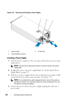
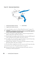
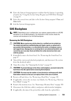
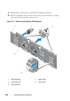
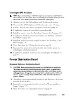
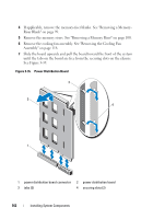
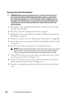
Installing the SAS Backplane NOTE: If you are installing an x16 SAS backplane, you must remove all the three chassis blanks from the system. If you are installing an x4 SAS backplane, you must ensure that all the three chassis blanks are installed in the system. 1 Align the slots on the SAS backplane with the tabs on the chassis. 2 Slide down the SAS backplane until the release pin snaps into place. 3 Connect the SAS data cable(s) and power cable to the backplane. 4 If applicable, connect the optical drive power/data cable. 5 Install the memory risers. See "Installing a Memory Riser" on page 101. 6 If applicable, install the memory-riser blanks. See "Installing a Memory- Riser Blank" on page 100. 7 Install the hard drives in their original locations. See "Installing a Hard Drive" on page 110. 8 Close the system. See "Closing the System" on page 90. 9 Reconnect the system to its electrical outlet and turn the system on, including any attached peripherals. 10 If applicable, install the front bezel. See "Installing the Front Bezel" on page 87. Power Distribution Board Removing the Power Distribution Board CAUTION: Many repairs may only be done by a certified service technician. You should only perform troubleshooting and simple repairs as authorized in your product documentation, or as directed by the online or telephone service and support team. Damage due to servicing that is not authorized by Dell is not covered by your warranty. Read and follow the safety instructions that came with the product. 1 Turn off the system and attached peripherals, and disconnect the system from the electrical outlet. 2 Remove the power supplies from the system. See "Removing a Power Supply" on page 155. 3 Open the system. See "Opening the System" on page 89. Installing System Components 161
-
 1
1 -
2
-
3
-
4
-
5
-
6
-
7
-
8
-
9
-
10
-
11
-
12
-
13
-
14
-
15
-
16
-
17
-
18
-
19
-
20
-
21
-
22
-
23
-
24
-
25
-
26
-
27
-
28
-
29
-
30
-
31
-
32
-
33
-
34
-
35
-
36
-
37
-
38
-
39
-
40
-
41
-
42
-
43
-
44
-
45
-
46
-
47
-
48
-
49
-
50
-
51
-
52
-
53
-
54
-
55
-
56
-
57
-
58
-
59
-
60
-
61
-
62
-
63
-
64
-
65
-
66
-
67
-
68
-
69
-
70
-
71
-
72
-
73
-
74
-
75
-
76
-
77
-
78
-
79
-
80
-
81
-
82
-
83
-
84
-
85
-
86
-
87
-
88
-
89
-
90
-
91
-
92
-
93
-
94
-
95
-
96
-
97
-
98
-
99
-
100
-
101
-
102
-
103
-
104
-
105
-
106
-
107
-
108
-
109
-
110
-
111
-
112
-
113
-
114
-
115
-
116
-
117
-
118
-
119
-
120
-
121
-
122
-
123
-
124
-
125
-
126
-
127
-
128
-
129
-
130
-
131
-
132
-
133
-
134
-
135
-
136
-
137
-
138
-
139
-
140
-
141
-
142
-
143
-
144
-
145
-
146
-
147
-
148
-
149
-
150
-
151
-
152
-
153
-
154
-
155
-
 156
156 -
 157
157 -
 158
158 -
 159
159 -
 160
160 -
 161
161 -
 162
162 -
 163
163 -
 164
164 -
 165
165 -
 166
166 -
167
-
168
-
169
-
170
-
171
-
172
-
173
-
174
-
175
-
176
-
177
-
178
-
179
-
180
-
181
-
182
-
183
-
184
-
185
-
186
-
187
-
188
-
189
-
190
-
191
-
192
-
193
-
194
-
195
-
196
-
197
-
198
-
199
-
200
-
201
-
202
-
203
-
204
-
205
-
206
-
207
-
208
-
209
-
210
 |
 |