Dell PowerEdge R910 Hardware Owner's Manual - Page 113
Installing a Hard Drive Into a Drive Carrier, Optical Drive, Removing an Optical Drive
 |
View all Dell PowerEdge R910 manuals
Add to My Manuals
Save this manual to your list of manuals |
Page 113 highlights
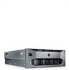
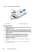
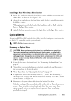
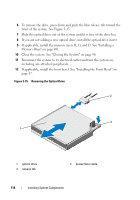
Installing a Hard Drive Into a Drive Carrier 1 Insert the hard drive into the hard-drive carrier with the connector end of the drive at the rear. See Figure 3-14. 2 Align the screw holes on the hard drive with the back set of holes on the hard drive carrier. When aligned correctly, the back of the hard drive will be flush with the back of the hard-drive carrier. 3 Attach the four screws to secure the hard drive to the hard-drive carrier. Optical Drive An optional DVD +/-RW optical drive slides into the front panel and connects to the SATA controller on the system board. NOTE: DVD devices are data only. Removing an Optical Drive CAUTION: Many repairs may only be done by a certified service technician. You should only perform troubleshooting and simple repairs as authorized in your product documentation, or as directed by the online or telephone service and support team. Damage due to servicing that is not authorized by Dell is not covered by your warranty. Read and follow the safety instructions that came with the product. 1 If installed, remove the front bezel. See "Removing the Front Bezel" on page 87. 2 Turn off the system, including any attached peripherals, and disconnect the system from its electrical outlet. 3 Open the system. See "Opening the System" on page 89. 4 If applicable, remove the memory risers H, G, and D. See "Removing a Memory Riser" on page 100. For the location of memory risers H, G, and D on the system, see Figure 3-5. 5 Disconnect the power/data cable from the back of the drive. Note the routing of the power/data cable on the side on the system as you remove them from the system board and drive. You must route these cables properly when you replace them to prevent them from being pinched or crimped. Installing System Components 113
-
 1
1 -
2
-
3
-
4
-
5
-
6
-
7
-
8
-
9
-
10
-
11
-
12
-
13
-
14
-
15
-
16
-
17
-
18
-
19
-
20
-
21
-
22
-
23
-
24
-
25
-
26
-
27
-
28
-
29
-
30
-
31
-
32
-
33
-
34
-
35
-
36
-
37
-
38
-
39
-
40
-
41
-
42
-
43
-
44
-
45
-
46
-
47
-
48
-
49
-
50
-
51
-
52
-
53
-
54
-
55
-
56
-
57
-
58
-
59
-
60
-
61
-
62
-
63
-
64
-
65
-
66
-
67
-
68
-
69
-
70
-
71
-
72
-
73
-
74
-
75
-
76
-
77
-
78
-
79
-
80
-
81
-
82
-
83
-
84
-
85
-
86
-
87
-
88
-
89
-
90
-
91
-
92
-
93
-
94
-
95
-
96
-
97
-
98
-
99
-
100
-
101
-
102
-
103
-
104
-
105
-
106
-
107
-
 108
108 -
 109
109 -
 110
110 -
 111
111 -
 112
112 -
 113
113 -
 114
114 -
 115
115 -
 116
116 -
 117
117 -
 118
118 -
119
-
120
-
121
-
122
-
123
-
124
-
125
-
126
-
127
-
128
-
129
-
130
-
131
-
132
-
133
-
134
-
135
-
136
-
137
-
138
-
139
-
140
-
141
-
142
-
143
-
144
-
145
-
146
-
147
-
148
-
149
-
150
-
151
-
152
-
153
-
154
-
155
-
156
-
157
-
158
-
159
-
160
-
161
-
162
-
163
-
164
-
165
-
166
-
167
-
168
-
169
-
170
-
171
-
172
-
173
-
174
-
175
-
176
-
177
-
178
-
179
-
180
-
181
-
182
-
183
-
184
-
185
-
186
-
187
-
188
-
189
-
190
-
191
-
192
-
193
-
194
-
195
-
196
-
197
-
198
-
199
-
200
-
201
-
202
-
203
-
204
-
205
-
206
-
207
-
208
-
209
-
210
 |
 |