Dell PowerEdge R910 Hardware Owner's Manual - Page 199
Table 6-2., System Board Jumpers and Connectors, Connector, Description, PCIE_G2_X4
 |
View all Dell PowerEdge R910 manuals
Add to My Manuals
Save this manual to your list of manuals |
Page 199 highlights
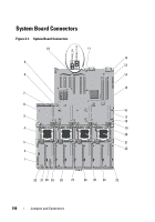
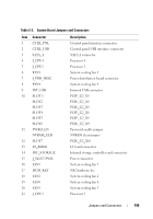
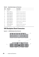
Table 6-2. System Board Jumpers and Connectors Item Connector 1 CTRL_PNL 2 CTRL_USB 3 SATA_A 4 J_CPU4 5 J_CPU2 6 FAN1 7 J_PDB_MISC 8 FAN4 9 INT_USB 10 SLOT 1 SLOT2 SLOT3 SLOT4 SLOT5 SLOT6 11 PWRD_EN NVRAM_CLR 12 SLOT7 13 IO_RISER 14 INT_STORAGE 15 J_SLOT7PWR 16 FAN5 17 ISCSI_KEY 18 FAN2 19 FAN6 20 FAN3 21 J_CPU3 Description Control panel interface connector Control panel USB interface connector SATA A connector Processor 4 Processor 2 System cooling fan 1 Power distribution board connector System cooling fan 4 Internal USB connector PCIE_G2_X4 PCIE_G2_X8 PCIE_G2_X8 PCIE_G2_X8 PCIE_G2_X4 PCIE_G2_X4 Password enable jumper NVRAM clear jumper PCIE_G2_X16 I/O card connector Internal storage controller card connector Power connector System cooling fan 5 NIC hardware key System cooling fan 2 System cooling fan 6 System cooling fan 3 Processor 3 Jumpers and Connectors 199
-
 1
1 -
2
-
3
-
4
-
5
-
6
-
7
-
8
-
9
-
10
-
11
-
12
-
13
-
14
-
15
-
16
-
17
-
18
-
19
-
20
-
21
-
22
-
23
-
24
-
25
-
26
-
27
-
28
-
29
-
30
-
31
-
32
-
33
-
34
-
35
-
36
-
37
-
38
-
39
-
40
-
41
-
42
-
43
-
44
-
45
-
46
-
47
-
48
-
49
-
50
-
51
-
52
-
53
-
54
-
55
-
56
-
57
-
58
-
59
-
60
-
61
-
62
-
63
-
64
-
65
-
66
-
67
-
68
-
69
-
70
-
71
-
72
-
73
-
74
-
75
-
76
-
77
-
78
-
79
-
80
-
81
-
82
-
83
-
84
-
85
-
86
-
87
-
88
-
89
-
90
-
91
-
92
-
93
-
94
-
95
-
96
-
97
-
98
-
99
-
100
-
101
-
102
-
103
-
104
-
105
-
106
-
107
-
108
-
109
-
110
-
111
-
112
-
113
-
114
-
115
-
116
-
117
-
118
-
119
-
120
-
121
-
122
-
123
-
124
-
125
-
126
-
127
-
128
-
129
-
130
-
131
-
132
-
133
-
134
-
135
-
136
-
137
-
138
-
139
-
140
-
141
-
142
-
143
-
144
-
145
-
146
-
147
-
148
-
149
-
150
-
151
-
152
-
153
-
154
-
155
-
156
-
157
-
158
-
159
-
160
-
161
-
162
-
163
-
164
-
165
-
166
-
167
-
168
-
169
-
170
-
171
-
172
-
173
-
174
-
175
-
176
-
177
-
178
-
179
-
180
-
181
-
182
-
183
-
184
-
185
-
186
-
187
-
188
-
189
-
190
-
191
-
192
-
193
-
 194
194 -
 195
195 -
 196
196 -
 197
197 -
 198
198 -
 199
199 -
 200
200 -
 201
201 -
 202
202 -
 203
203 -
 204
204 -
205
-
206
-
207
-
208
-
209
-
210
 |
 |