Dell PowerEdge R910 Hardware Owner's Manual - Page 162
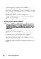
See Slide the board upwards and pull the board toward the front of the system
 |
View all Dell PowerEdge R910 manuals
Add to My Manuals
Save this manual to your list of manuals |
Page 162 highlights
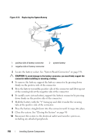
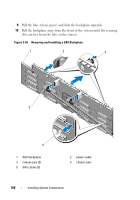
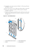
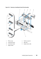
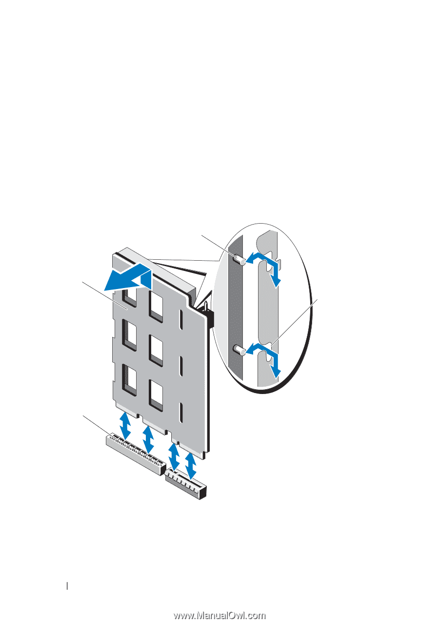
4 If applicable, remove the memory-riser blanks. See "Removing a MemoryRiser Blank" on page 99. 5 Remove the memory risers. See "Removing a Memory Riser" on page 100. 6 Remove the cooling fan assembly. See "Removing the Cooling Fan Assembly" on page 118. 7 Slide the board upwards and pull the board toward the front of the system until the tabs on the board are free from the securing slots on the chassis. See Figure 3-35. Figure 3-35. Power Distribution Board 3 2 4 1 1 power distribution board connector 3 tabs (2) 2 power distribution board 4 securing slots (2) 162 Installing System Components
-
 1
1 -
2
-
3
-
4
-
5
-
6
-
7
-
8
-
9
-
10
-
11
-
12
-
13
-
14
-
15
-
16
-
17
-
18
-
19
-
20
-
21
-
22
-
23
-
24
-
25
-
26
-
27
-
28
-
29
-
30
-
31
-
32
-
33
-
34
-
35
-
36
-
37
-
38
-
39
-
40
-
41
-
42
-
43
-
44
-
45
-
46
-
47
-
48
-
49
-
50
-
51
-
52
-
53
-
54
-
55
-
56
-
57
-
58
-
59
-
60
-
61
-
62
-
63
-
64
-
65
-
66
-
67
-
68
-
69
-
70
-
71
-
72
-
73
-
74
-
75
-
76
-
77
-
78
-
79
-
80
-
81
-
82
-
83
-
84
-
85
-
86
-
87
-
88
-
89
-
90
-
91
-
92
-
93
-
94
-
95
-
96
-
97
-
98
-
99
-
100
-
101
-
102
-
103
-
104
-
105
-
106
-
107
-
108
-
109
-
110
-
111
-
112
-
113
-
114
-
115
-
116
-
117
-
118
-
119
-
120
-
121
-
122
-
123
-
124
-
125
-
126
-
127
-
128
-
129
-
130
-
131
-
132
-
133
-
134
-
135
-
136
-
137
-
138
-
139
-
140
-
141
-
142
-
143
-
144
-
145
-
146
-
147
-
148
-
149
-
150
-
151
-
152
-
153
-
154
-
155
-
156
-
 157
157 -
 158
158 -
 159
159 -
 160
160 -
 161
161 -
 162
162 -
 163
163 -
 164
164 -
 165
165 -
 166
166 -
 167
167 -
168
-
169
-
170
-
171
-
172
-
173
-
174
-
175
-
176
-
177
-
178
-
179
-
180
-
181
-
182
-
183
-
184
-
185
-
186
-
187
-
188
-
189
-
190
-
191
-
192
-
193
-
194
-
195
-
196
-
197
-
198
-
199
-
200
-
201
-
202
-
203
-
204
-
205
-
206
-
207
-
208
-
209
-
210
 |
 |
162
Installing System Components
4
If applicable, remove the memory-riser blanks. See "Removing a Memory-
Riser Blank" on page 99.
5
Remove the memory risers. See "Removing a Memory Riser" on page 100.
6
Remove the cooling fan assembly. See "Removing the Cooling Fan
Assembly" on page 118.
7
Slide the board upwards and pull the board toward the front of the system
until the tabs on the board are free from the securing slots on the chassis.
See Figure 3-35.
Figure 3-35.
Power Distribution Board
1
power distribution board connector
2
power distribution board
3
tabs (2)
4
securing slots (2)
3
4
2
1