Dell PowerEdge R910 Hardware Owner's Manual - Page 14
LCD Panel Features - specifications
 |
View all Dell PowerEdge R910 manuals
Add to My Manuals
Save this manual to your list of manuals |
Page 14 highlights
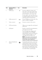
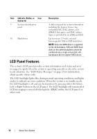
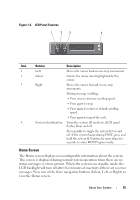
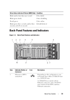
Item Indicator, Button, or Icon Connector 9 System identification panel 10 Hard drives Description A slide-out panel for system information including the Express Service tag, embedded NIC MAC address, and iDRAC6 Enterprise card MAC address. Space is provided for an additional label. Up to sixteen 2.5-inch, external hot-swappable SAS or SSD hard drives. NOTE: Only one SATA drive is supported on the x4 backplane. SAS and SATA hard disks on the same backplane cannot be combined into a single virtual disk. x16 backplanes do not support SATA drives. LCD Panel Features The system's LCD panel provides system information and status and error messages to signify when the system is operating correctly or when the system needs attention. See "LCD Status Messages" on page 23 for information about specific status codes. The LCD backlight lights blue during normal operating conditions and lights amber to indicate an error condition. When the system is in standby mode, the LCD backlight is off and can be turned on by pressing either the Select, Left or Right button on the LCD panel. The LCD backlight will remain off if LCD messaging is turned off through the iDRAC utility, the LCD panel, or other tools. 14 About Your System
-
 1
1 -
2
-
3
-
4
-
5
-
6
-
7
-
8
-
 9
9 -
 10
10 -
 11
11 -
 12
12 -
 13
13 -
 14
14 -
 15
15 -
 16
16 -
 17
17 -
 18
18 -
 19
19 -
20
-
21
-
22
-
23
-
24
-
25
-
26
-
27
-
28
-
29
-
30
-
31
-
32
-
33
-
34
-
35
-
36
-
37
-
38
-
39
-
40
-
41
-
42
-
43
-
44
-
45
-
46
-
47
-
48
-
49
-
50
-
51
-
52
-
53
-
54
-
55
-
56
-
57
-
58
-
59
-
60
-
61
-
62
-
63
-
64
-
65
-
66
-
67
-
68
-
69
-
70
-
71
-
72
-
73
-
74
-
75
-
76
-
77
-
78
-
79
-
80
-
81
-
82
-
83
-
84
-
85
-
86
-
87
-
88
-
89
-
90
-
91
-
92
-
93
-
94
-
95
-
96
-
97
-
98
-
99
-
100
-
101
-
102
-
103
-
104
-
105
-
106
-
107
-
108
-
109
-
110
-
111
-
112
-
113
-
114
-
115
-
116
-
117
-
118
-
119
-
120
-
121
-
122
-
123
-
124
-
125
-
126
-
127
-
128
-
129
-
130
-
131
-
132
-
133
-
134
-
135
-
136
-
137
-
138
-
139
-
140
-
141
-
142
-
143
-
144
-
145
-
146
-
147
-
148
-
149
-
150
-
151
-
152
-
153
-
154
-
155
-
156
-
157
-
158
-
159
-
160
-
161
-
162
-
163
-
164
-
165
-
166
-
167
-
168
-
169
-
170
-
171
-
172
-
173
-
174
-
175
-
176
-
177
-
178
-
179
-
180
-
181
-
182
-
183
-
184
-
185
-
186
-
187
-
188
-
189
-
190
-
191
-
192
-
193
-
194
-
195
-
196
-
197
-
198
-
199
-
200
-
201
-
202
-
203
-
204
-
205
-
206
-
207
-
208
-
209
-
210
 |
 |