Dell PowerEdge R910 Hardware Owner's Manual - Page 158
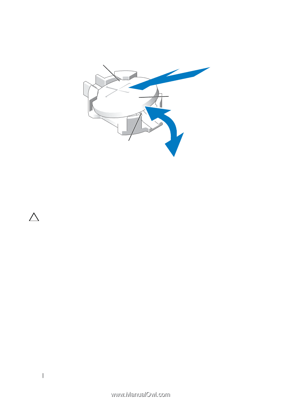
down firmly on the positive side of the connector., To install a new system battery
 |
View all Dell PowerEdge R910 manuals
Add to My Manuals
Save this manual to your list of manuals |
Page 158 highlights
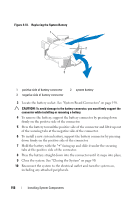
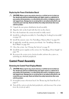
Figure 3-33. Replacing the System Battery 1 2 3 1 positive side of battery connector 3 negative side of battery connector 2 system battery 3 Locate the battery socket. See "System Board Connectors" on page 198. CAUTION: To avoid damage to the battery connector, you must firmly support the connector while installing or removing a battery. 4 To remove the battery, support the battery connector by pressing down firmly on the positive side of the connector. 5 Press the battery toward the positive side of the connector and lift it up out of the securing tabs at the negative side of the connector. 6 To install a new system battery, support the battery connector by pressing down firmly on the positive side of the connector. 7 Hold the battery with the "+" facing up and slide it under the securing tabs at the positive side of the connector. 8 Press the battery straight down into the connector until it snaps into place. 9 Close the system. See "Closing the System" on page 90. 10 Reconnect the system to the electrical outlet and turn the system on, including any attached peripherals. 158 Installing System Components
-
 1
1 -
2
-
3
-
4
-
5
-
6
-
7
-
8
-
9
-
10
-
11
-
12
-
13
-
14
-
15
-
16
-
17
-
18
-
19
-
20
-
21
-
22
-
23
-
24
-
25
-
26
-
27
-
28
-
29
-
30
-
31
-
32
-
33
-
34
-
35
-
36
-
37
-
38
-
39
-
40
-
41
-
42
-
43
-
44
-
45
-
46
-
47
-
48
-
49
-
50
-
51
-
52
-
53
-
54
-
55
-
56
-
57
-
58
-
59
-
60
-
61
-
62
-
63
-
64
-
65
-
66
-
67
-
68
-
69
-
70
-
71
-
72
-
73
-
74
-
75
-
76
-
77
-
78
-
79
-
80
-
81
-
82
-
83
-
84
-
85
-
86
-
87
-
88
-
89
-
90
-
91
-
92
-
93
-
94
-
95
-
96
-
97
-
98
-
99
-
100
-
101
-
102
-
103
-
104
-
105
-
106
-
107
-
108
-
109
-
110
-
111
-
112
-
113
-
114
-
115
-
116
-
117
-
118
-
119
-
120
-
121
-
122
-
123
-
124
-
125
-
126
-
127
-
128
-
129
-
130
-
131
-
132
-
133
-
134
-
135
-
136
-
137
-
138
-
139
-
140
-
141
-
142
-
143
-
144
-
145
-
146
-
147
-
148
-
149
-
150
-
151
-
152
-
 153
153 -
 154
154 -
 155
155 -
 156
156 -
 157
157 -
 158
158 -
 159
159 -
 160
160 -
 161
161 -
 162
162 -
 163
163 -
164
-
165
-
166
-
167
-
168
-
169
-
170
-
171
-
172
-
173
-
174
-
175
-
176
-
177
-
178
-
179
-
180
-
181
-
182
-
183
-
184
-
185
-
186
-
187
-
188
-
189
-
190
-
191
-
192
-
193
-
194
-
195
-
196
-
197
-
198
-
199
-
200
-
201
-
202
-
203
-
204
-
205
-
206
-
207
-
208
-
209
-
210
 |
 |