Dell PowerEdge R910 Hardware Owner's Manual - Page 150
Position your thumb firmly over the processor socket-release lever
 |
View all Dell PowerEdge R910 manuals
Add to My Manuals
Save this manual to your list of manuals |
Page 150 highlights
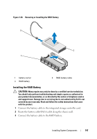
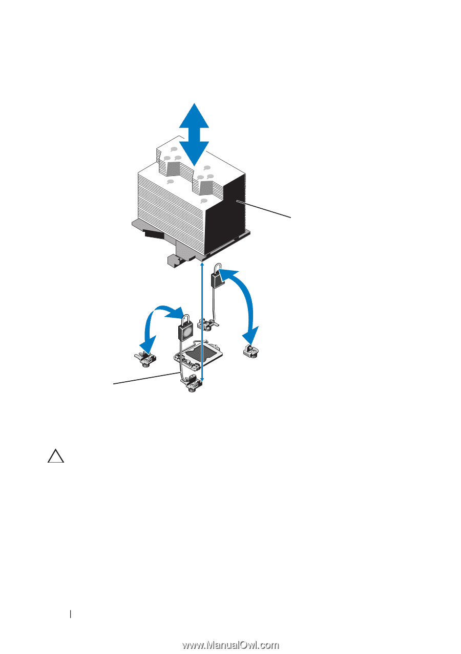
Figure 3-29. Installing and Removing the Heat Sink 2 1 1 release levers (2) 2 heat sink CAUTION: The processor is held in its socket under strong pressure. Be aware that the release lever can spring up suddenly if not firmly grasped. 11 Position your thumb firmly over the processor socket-release lever and release the lever from the locked position by pushing down and pulling out from under the tab. Rotate the lever 90 degrees upward until the processor is released from the socket. See Figure 3-29. 12 Use the tab on the processor shield to rotate shield upward and out of the way. See Figure 3-29. 150 Installing System Components
-
 1
1 -
2
-
3
-
4
-
5
-
6
-
7
-
8
-
9
-
10
-
11
-
12
-
13
-
14
-
15
-
16
-
17
-
18
-
19
-
20
-
21
-
22
-
23
-
24
-
25
-
26
-
27
-
28
-
29
-
30
-
31
-
32
-
33
-
34
-
35
-
36
-
37
-
38
-
39
-
40
-
41
-
42
-
43
-
44
-
45
-
46
-
47
-
48
-
49
-
50
-
51
-
52
-
53
-
54
-
55
-
56
-
57
-
58
-
59
-
60
-
61
-
62
-
63
-
64
-
65
-
66
-
67
-
68
-
69
-
70
-
71
-
72
-
73
-
74
-
75
-
76
-
77
-
78
-
79
-
80
-
81
-
82
-
83
-
84
-
85
-
86
-
87
-
88
-
89
-
90
-
91
-
92
-
93
-
94
-
95
-
96
-
97
-
98
-
99
-
100
-
101
-
102
-
103
-
104
-
105
-
106
-
107
-
108
-
109
-
110
-
111
-
112
-
113
-
114
-
115
-
116
-
117
-
118
-
119
-
120
-
121
-
122
-
123
-
124
-
125
-
126
-
127
-
128
-
129
-
130
-
131
-
132
-
133
-
134
-
135
-
136
-
137
-
138
-
139
-
140
-
141
-
142
-
143
-
144
-
 145
145 -
 146
146 -
 147
147 -
 148
148 -
 149
149 -
 150
150 -
 151
151 -
 152
152 -
 153
153 -
 154
154 -
 155
155 -
156
-
157
-
158
-
159
-
160
-
161
-
162
-
163
-
164
-
165
-
166
-
167
-
168
-
169
-
170
-
171
-
172
-
173
-
174
-
175
-
176
-
177
-
178
-
179
-
180
-
181
-
182
-
183
-
184
-
185
-
186
-
187
-
188
-
189
-
190
-
191
-
192
-
193
-
194
-
195
-
196
-
197
-
198
-
199
-
200
-
201
-
202
-
203
-
204
-
205
-
206
-
207
-
208
-
209
-
210
 |
 |
150
Installing System Components
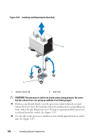
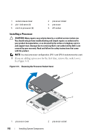
Figure 3-29.
Installing and Removing the Heat Sink
CAUTION:
The processor is held in its socket under strong pressure. Be aware
that the release lever can spring up suddenly if not firmly grasped.
11
Position your thumb firmly over the processor socket-release lever and
release the lever from the locked position by pushing down and pulling out
from under the tab. Rotate the lever 90 degrees upward until the processor
is released from the socket. See Figure 3-29.
12
Use the tab on the processor shield to rotate shield upward and out of the
way. See Figure 3-29.
1
release levers (2)
2
heat sink
1
2